


We turn architectural and structural design into coordinated, fabrication-ready LGS framing packages. Our team develops structural layouts, panelized assemblies, shop drawings, BOMs, and CNC-ready production data tailored to your roll-former, profiles, tooling, and fabrication standards.
Why model-driven LGSF detailing matters?
Panelized LGSF performs best when engineering, detailing, coordination, and CNC production data are connected before fabrication. ORIGIN aligns design intent, roll-former constraints, and site installation requirements to deliver predictable accuracy from plant to jobsite.
0
Completed engineering projects involving calculations, LGS shop drawings, CNC outputs, and structural steel shop drawings
0
Potential reduction in hot-rolled steel through engineered built-up LGS assemblies
0
Less rework and fewer site issues when framing is detailed, reviewed, and clash-checked before release to CNC
0
Scope and fee estimate within one business day after input files are received
From engineering to CNC-ready production data
ORIGIN supports the full LGSF workflow — from feasibility review and structural calculations to coordinated BIM models, truss packages, fabrication drawings, BOMs, and CNC-ready production data.
Each framing system is developed around your profiles, steel thicknesses, roll-forming equipment, internal standards, and fabrication practices.
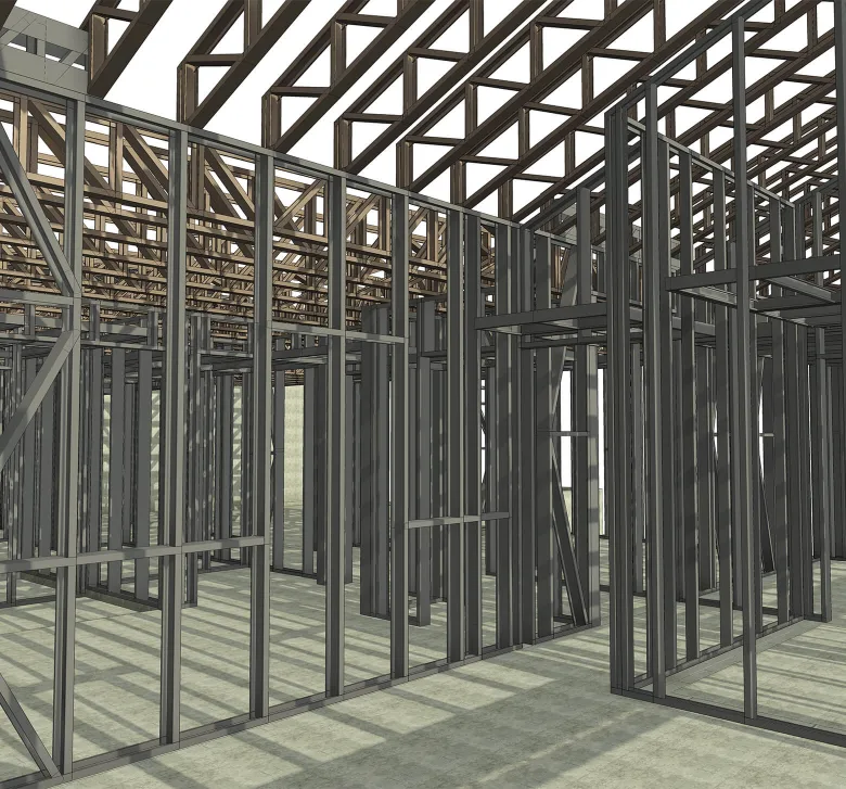
The problem
Conventional 2D LGS shop drawings are often developed from architectural or structural documents that leave critical interfaces unresolved. MEP routing, architectural features, structural details, openings, tolerances, and manufacturer-specific requirements are not always reviewed as one coordinated system before fabrication.
Unlike conventional stick framing, panelized LGSF depends on controlled decisions before production. Late changes can still be absorbed, but they often come at the cost of RFIs, field fixes, rework, schedule delays, and deviation from the approved design intent.
Without coordinated layouts and controlled release documentation, the result is predictable:
- LGS elements may not align with the structure, or intended architectural features cannot be delivered as designed.
- Openings and MEP penetrations are coordinated too late → field fixes, urgent RFIs, and rework.
- Connection and tolerance details are not adapted to the manufacturer’s workflow → confusion and delays on site.
- Framing progress and final fit depend too heavily on on-site labor and field interpretation → higher risk of deviating from the approved design intent.
How ORIGIN solves LGSF coordination before fabrication
Engineering aligned with actual plant capabilities
Before detailed design, we check the framing approach against the client’s actual production setup: available steel thicknesses, coil inventory, profile sizes, steel grades, roll-former capabilities, and tooling configuration.
This helps ensure that the proposed LGSF system can be manufactured using the client’s existing materials, equipment, and fabrication process — rather than creating a theoretically correct package that is difficult to produce in practice.
Documentation adapted to the client’s LGS standards
Many LGS manufacturers already have established details, profile combinations, connection methods, panelization rules, naming conventions, and drawing standards.
We adapt the model, documentation, and production outputs to these existing practices, so the client does not need to change their internal workflow or adopt a fixed external system.
Structural engineering beyond wall-panel detailing
Our scope is not limited to modeling wall panels or preparing shop drawings. LGS framing can be developed together with foundations, supporting steel, portal frames, moment frames, transfer structures, and other primary structural elements.
This allows the framing package to be coordinated as part of the complete load-bearing system, rather than treated as an isolated detailing task.
Practical reduction of hot-rolled steel
Where structurally and commercially justified, selected hot-rolled steel elements can be replaced with engineered built-up LGS assemblies.
Depending on the structural requirements, this may include bundled studs, back-to-back profiles, boxed sections, built-up beams and headers, multi-profile columns, or reinforced truss assemblies.
Hot-rolled steel is retained where it is structurally or commercially justified, but it is not introduced automatically when a practical cold-formed steel solution is available.
Roof and truss design integrated into the structural system
We have extensive experience with roof framing and cold-formed steel trusses, including complex roof geometry, large openings, concentrated loads, girder trusses, load-transfer zones, and local multi-profile reinforcement.
Truss design is coordinated as part of the overall structural system and can be issued as a complete engineered truss package where required.
Critical coordination resolved before fabrication release
We do not develop the framing in isolation. Architectural geometry, rough openings, stairs, shafts, MEP routes, service penetrations, and equipment clearances are reviewed before the package is released for fabrication.
The sign-off process allows the architect and project team to confirm critical geometry before shop drawings and CNC files are finalized.
CNC output configured for the selected roll-former workflow
The workflow is not tied to a single roll-former manufacturer. Output can be prepared for Howick systems and other machines that accept CSV-based production data.
The command structure is configured around the client’s profiles, tooling operations, punching requirements, fabrication logic, and member identification rules.
Support across the full LGSF workflow
Our involvement can begin with an early feasibility review and continue through structural engineering, BIM modeling, coordination, sign-off drawings, truss packages, fabrication documentation, BOMs, and CNC-ready production data.
The engagement can cover the complete process or a specific stage that supplements the client’s internal engineering team.
Structure/Architecture
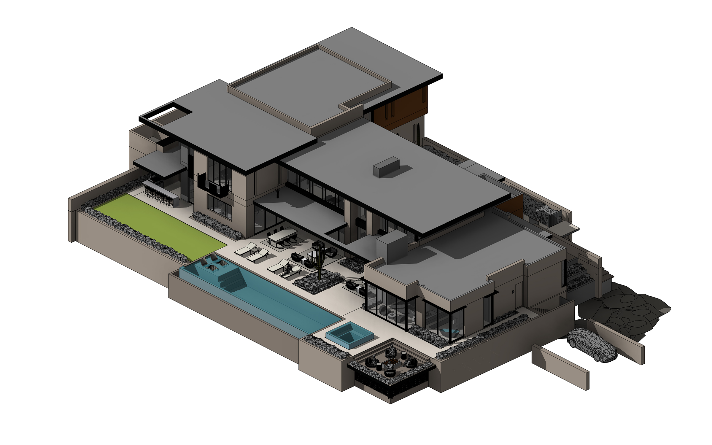
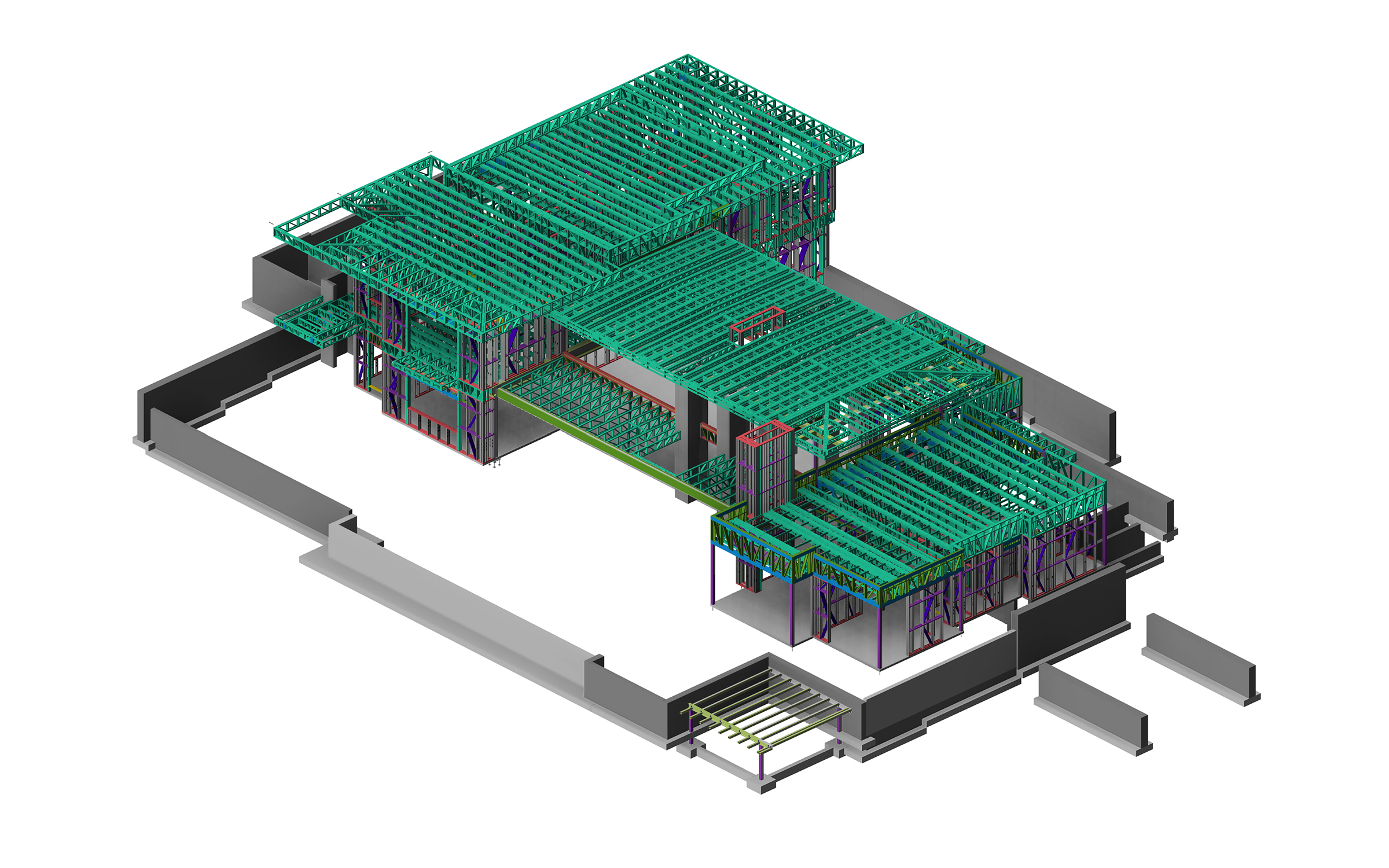
Our LGSF design and detailing deliverables
Explore a comprehensive package aligned to your plant, engineering, and site workflows.
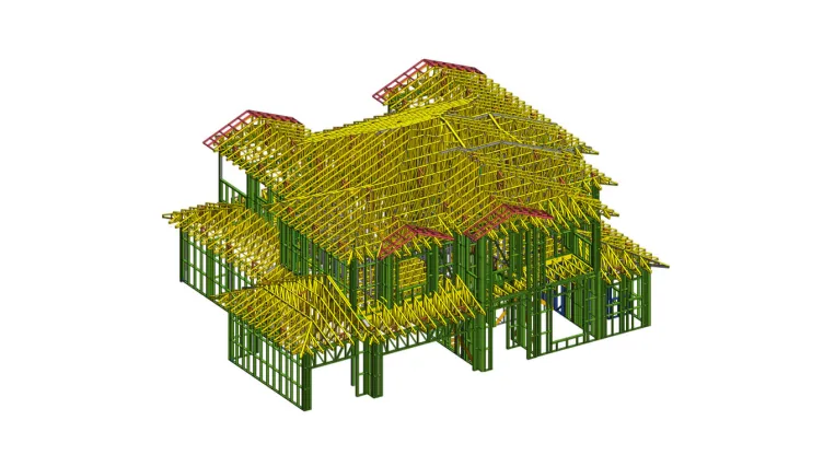
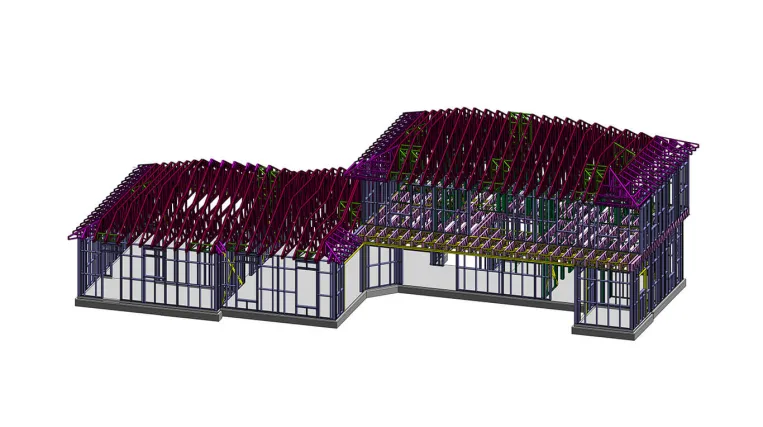
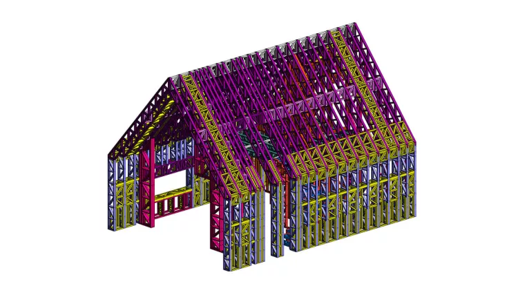
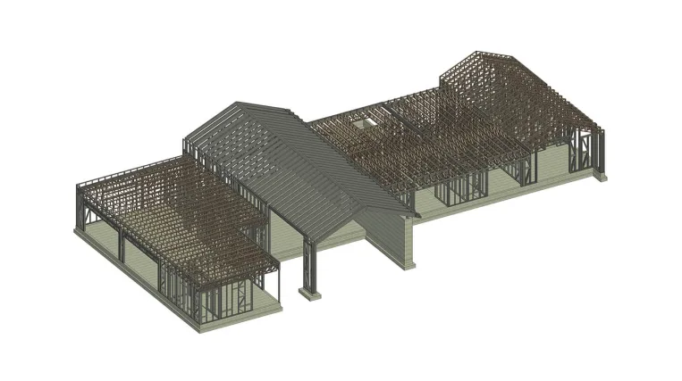
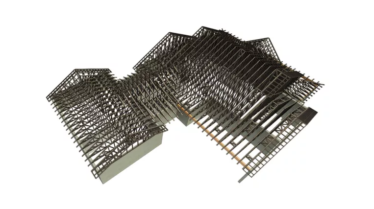
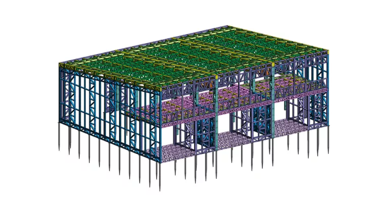
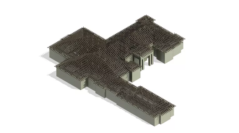
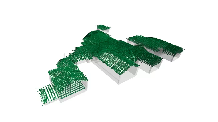
Related LGSF projects

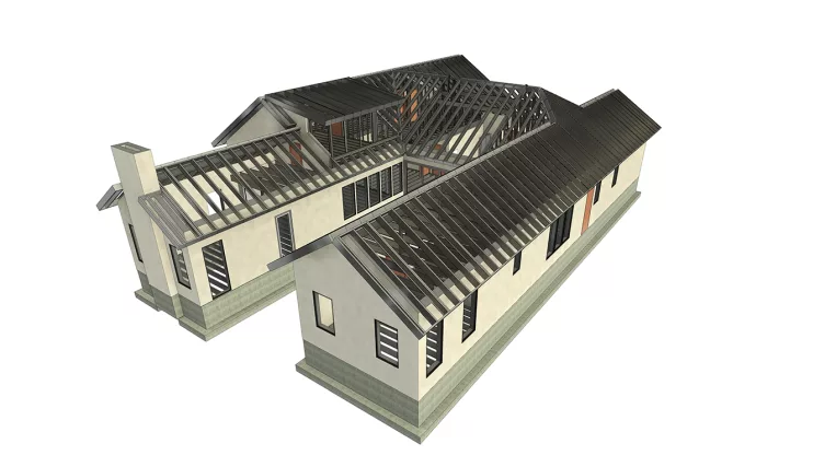
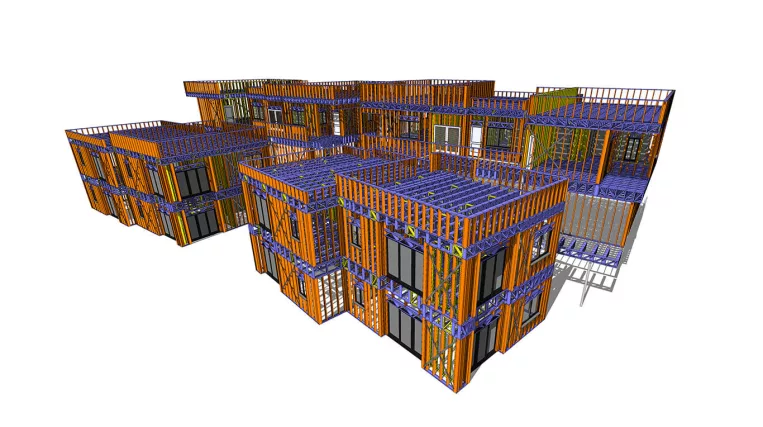
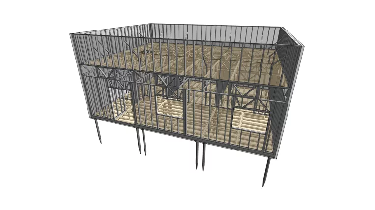
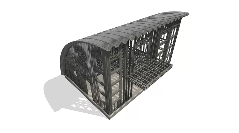
Software in use

Autodesk Revit

Autodesk Navisworks
Strucsoft MWF Advanced Metal

Tekla Structures
Tekla Tedds
SCIA Engineer
LGSF production and site assembly
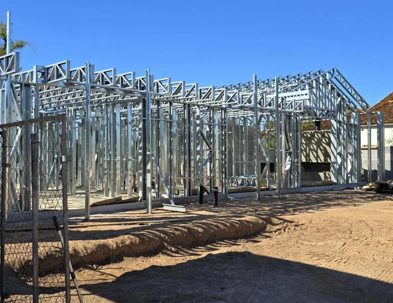
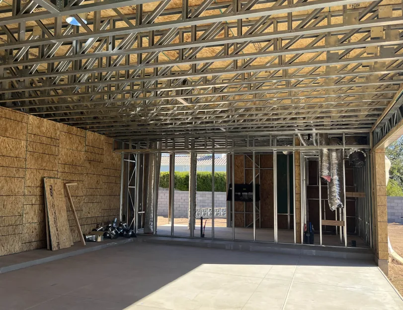
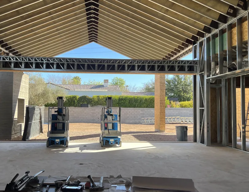
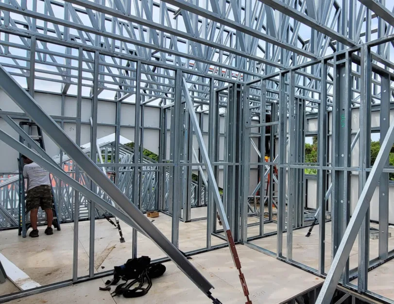
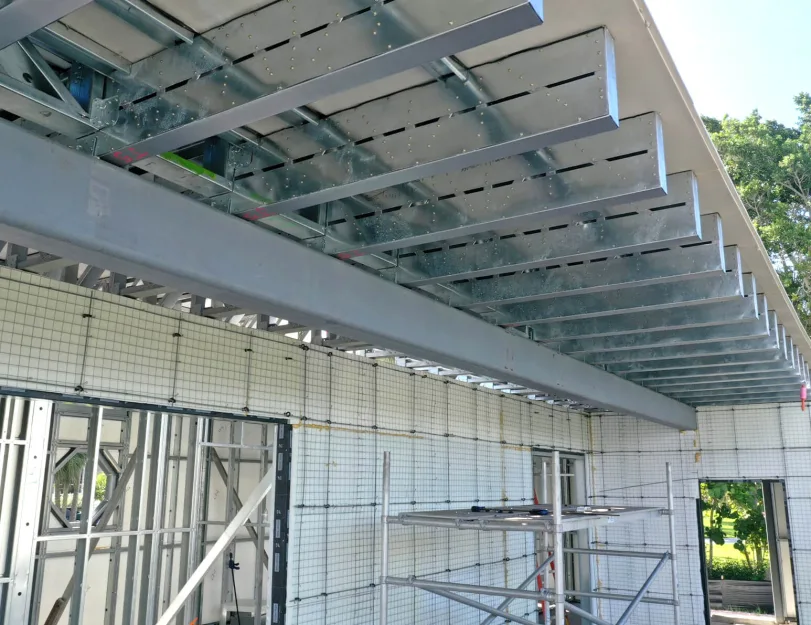
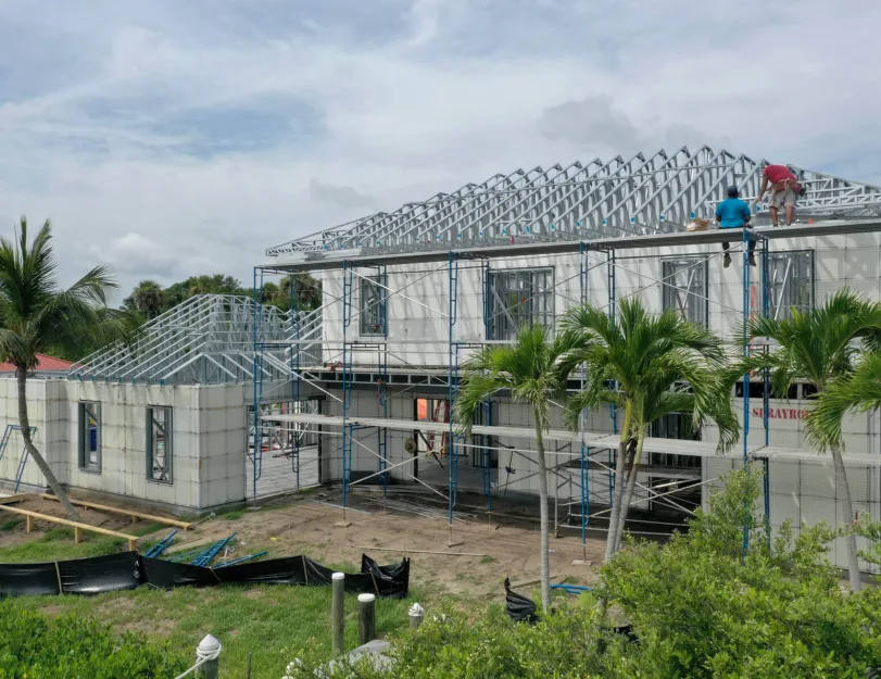
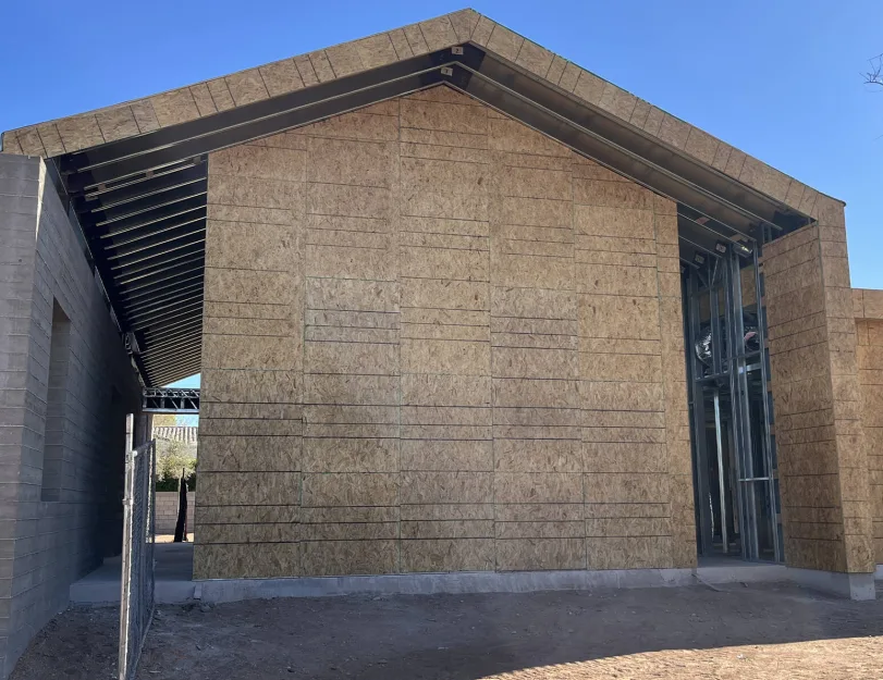
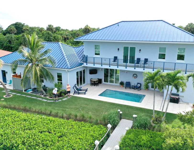
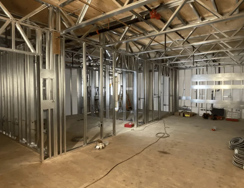
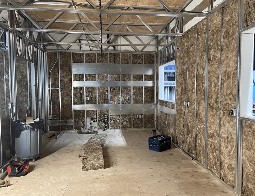
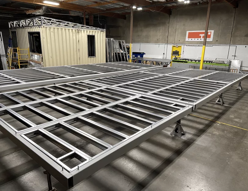
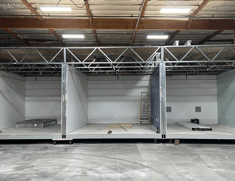
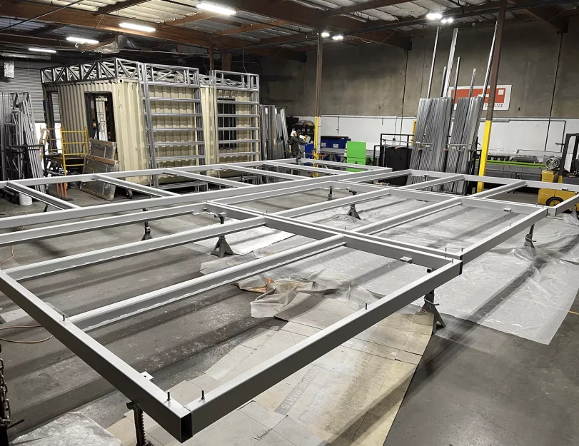
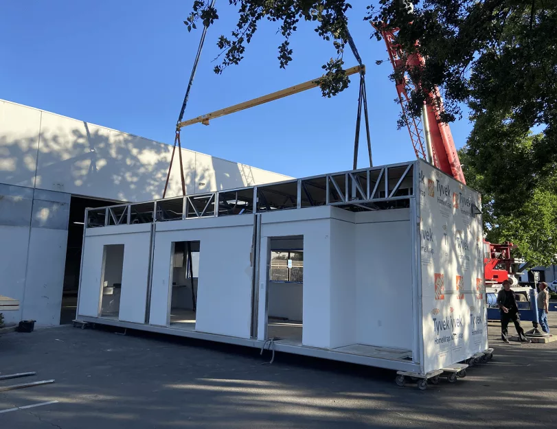
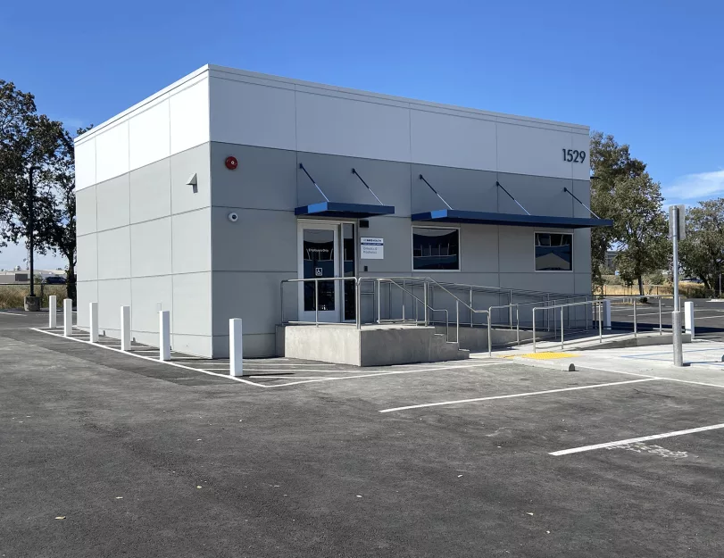
Real project photos showing light-gauge steel framing during production, site assembly, and installation before enclosure.

Who we work with
LGS manufacturers & fabricators
LGS manufacturers & fabricators
General & specialty contractors
Developers & owners
Architects & engineers (incl. EOR)
LGS manufacturers & fabricators
Manufacturing-aware LGS detailing and CNC production outputs aligned with selected roll-forming machines, profile systems, tooling, and internal production standards.
You receive:
- LGS shop and assembly drawings
- BOMs / cut lists
- Machine-specific CNC data issued with controlled revisions
General & specialty contractors
A coordinated structural package designed to install cleanly — without leaving crews to resolve clashes, assume connections, or coordinate MEP conflicts in the field.
You receive:
- Installation plans
- Coordinated structural set aligned with architectural and available MEP information
- Additional coordination plans or trade-specific review drawings where deeper site coordination is required
Developers & owners
Coordination is completed before fabrication, when decisions are cheaper to make and easier to control. This reduces the number of issues transferred to the jobsite, where they become RFIs, delays, rework, and change-driven cost.
You receive:
- Defined coordination and sign-off milestones
- Transparent decision documentation
- Fabrication-ready framing package that reduces reliance on last-minute field fixes
Architects & engineers (incl. EOR)
Your design intent is preserved — not simplified away. Structural framing is developed around the project’s key architectural and structural features, rather than forcing them into standard means and methods.
You receive:
- Coordination models
- Wall and rough-opening sign-offs
- Early-stage RFIs
- Clear communication of assumptions and items requiring further coordination
Our process
The process covers the full path from initial review to fabrication release, with engineering, coordination, and production requirements checked at each stage.
Feasibility & setup
We review architectural and structural documentation, project constraints, roll-former specifications, and manufacturer-specific requirements to confirm LGSF feasibility and define the preliminary framing approach.
This includes bearing walls, floor and roof framing, truss layouts, foundations, supporting steel, columns, transfer elements, and moment-resisting frames where required. Key framing conditions and open items are summarized for review by the client, architect, or structural engineer.
Structural development
Once the framing concept is agreed, we develop the complete structural system. This may include LGS walls, floors, roofs, trusses, built-up members, connections, foundations, and supporting hot-rolled steel.
Structural calculations are developed alongside the model and may cover either the full building or selected elements. Hybrid systems with portal frames, moment frames, transfer structures, and conventional structural steel are included where required.
Coordination & sign-offs
The framing model is coordinated with architectural, structural, and available MEP documentation before production release.
We review and resolve:
- Wall and bearing-line layouts
- Window and door rough openings
- Stairs and shafts
- Service penetrations
- MEP clearances
- Equipment locations
- Critical architectural geometry
Before production documentation is finalized, we issue sign-off drawings showing wall layouts, openings, dimensions, and framing geometry for review by the architect, client, or project team.
Permit & final engineering
Review comments from the client, Engineer of Record, or approving authority are incorporated into the structural package.
Final engineering deliverables may include:
- Structural calculations
- Construction or permit drawings
- Connection details
- Engineered truss package
- Shop drawings for supporting structural steel
Fabrication release
After the structural design and project geometry are approved, we prepare the production package for the selected fabrication workflow.
Depending on the scope, it may include:
- LGS shop drawings
- Wall, floor, and roof panel drawings
- Truss fabrication drawings
- Member and panel schedules
- BOMs
- Cut lists
- Manufacturer-specific CNC data
CNC output is configured for the client’s roll-forming equipment, available tooling, punching requirements, and required file structure.
Let’s connect
FAQ
What inputs do you accept?
We can work with architectural RVT, IFC, DWG, PDF drawings, structural documentation, soils reports, roll-former specifications, manufacturer-specific requirements, preferred connection details, and internal fabrication standards.
Can you provide structural engineering, calculations, and stamp-and-seal support?
Yes. We can provide structural calculations and stamp-and-seal services for LGS drawings and structural packages across the United States.
The documents are reviewed and sealed by a Professional Engineer licensed in the state where the project is located. Applicable jurisdiction, design codes, required submissions, and engineering responsibility are confirmed at the beginning of each project.
Can you customize CNC files for our roll former?
Yes. We can configure CNC output for the client’s specific roll-forming equipment, tooling setup, punching requirements, and required file structure.
We routinely prepare CNC outputs for Howick and FRAMECAD systems, and we can support other roll formers that accept configurable CSV-based input files. The command structure is adjusted according to the client’s profiles, tooling operations, service holes, dimples, cuts, connection features, and member identification requirements.
How do you handle tolerances and movement?
We document tolerances, movement joints, and interfaces with slabs, facade systems, foundations, supporting steel, and other adjacent building elements. Erection and installation drawings clarify sequencing, shim/adjust points, and critical coordination requirements where needed.
How do you handle MEP penetrations and openings?
Openings, service penetrations, MEP routes, equipment clearances, stairs, shafts, and critical architectural geometry are reviewed before production release. Penetrations and framed openings are modeled early and coordinated with available MEP information to reduce RFIs, field fixes, and late-stage rework.
What is the typical LOD and delivery format?
Typical modeling level is LOD 300–400, depending on the project scope and required deliverables.
Delivery formats may include Revit or Tekla models, LGS shop and assembly drawings, PDF/DWG drawing sets, BOMs, cut lists, CNC exports, IFC/NWC files for coordination, and manufacturer-specific production data.
What software do you use?
We use both Tekla Structures and Revit for LGS modeling, coordination, and drawing production.
Depending on the project scope, our workflow may also include:
- StrucSoft MWF Advanced Metal for LGS modeling, detailing, and truss-related workflows
- SCIA Engineer for analysis and design of the overall structural system
- IDEA StatiCa for connection design and local structural checks
The software environment is selected based on the client’s workflow, required deliverables, structural system, and fabrication setup.
How much do your LGS engineering services cost?
Each project is priced individually based on its size, structural complexity, available input documentation, required calculations, level of detailing, coordination scope, fabrication deliverables, and CNC requirements.
Once we receive the architectural and structural input files, we can usually provide a scope and fee estimate by the next business day.
How long does an LGS project take?
The timeline depends on the project size and complexity, input documentation quality, engineering scope, and number of coordination and approval rounds.
Before fabrication release, we review the architectural and structural documentation, coordinate wall layouts, bearing lines, rough openings, stairs, MEP clearances, penetrations, supporting steel, and other conditions that affect the framing package.
A detailed project timeline is prepared at the start of the work and agreed with the client. It identifies expected dates for the structural concept, coordination package, sign-off drawings, engineering deliverables, and fabrication release.
