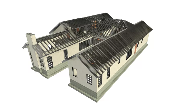
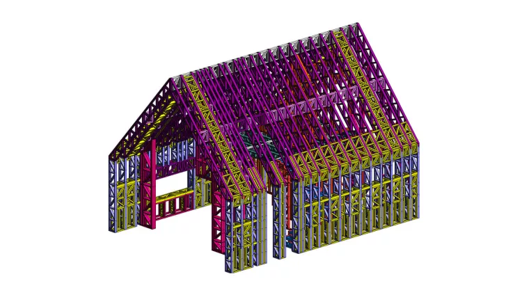
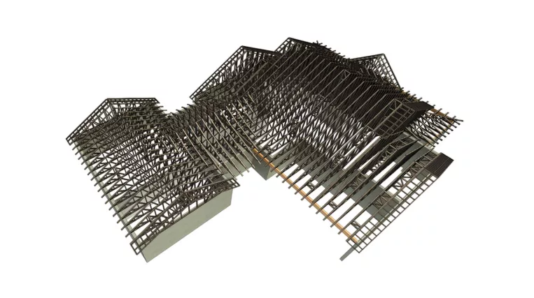
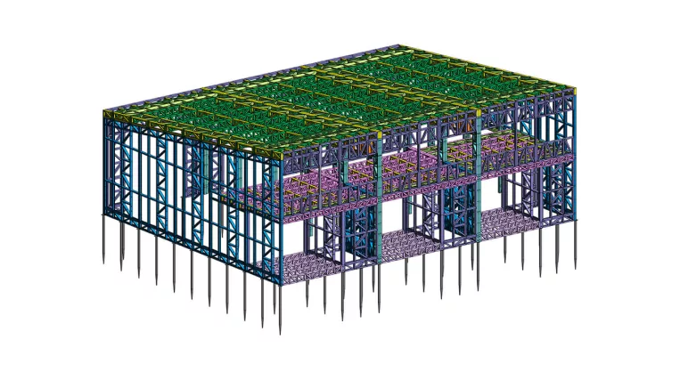
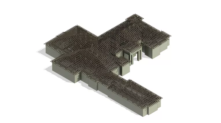
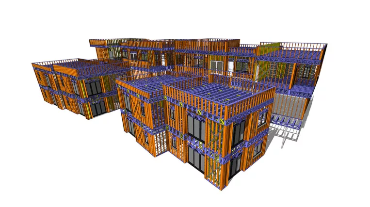
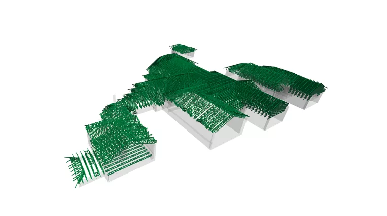
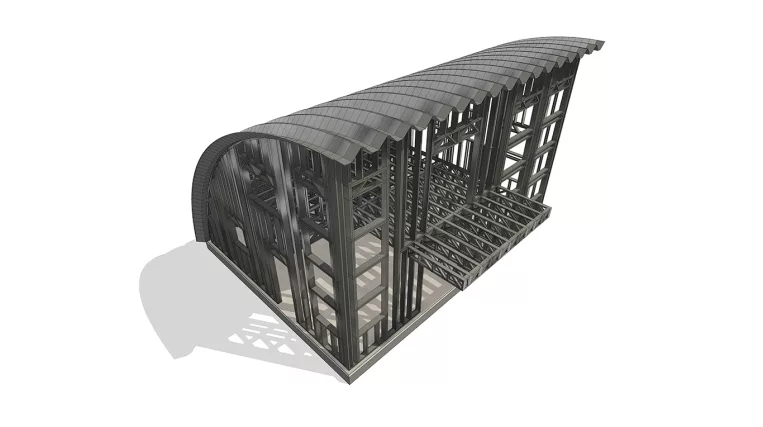
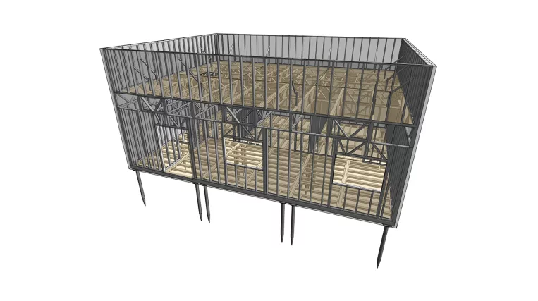
Structural engineering involves the design, analysis, and construction of structures to withstand various loads and stresses. In ORIGIN, we specialize in timber, CFS, and LGS framing, as well as structures made of classic red iron steel.

BIM modeling is the process of creating a 3D model that incorporates non-graphical information. Structural BIM models can be used by architects, engineers, contractors, and other stakeholders to plan, design, construct, and manage buildings or infrastructure assets.
Scan to BIM
In the context of structural engineering, laser scanning can be applied in the following cases:
Retrofit projects: Using a laser scanner allows for capturing existing conditions and performing precise point cloud conversion to a BIM model. Once the existing structure BIM model is completed, it becomes convenient to analyze it and make structural additions or modifications.
Geometry control: It is important to track the location of main structural members to avoid issues such as bolt mismatches or column tilt.
PDF/CAD to BIM conversion
Despite the beneficial process of creating drawings as an extraction from a BIM model, many companies still rely on a 2D approach for their designs. However, in certain cases, it becomes evident that a BIM model is necessary. This is where specialists from ORIGIN can assist.
The creation of a BIM model from 2D CAD or PDF files is a process that also helps in identifying issues and drawing mistakes when viewing the entire picture in 3D mode.
Structural design requires extensive experience, and in ORIGIN, our specialists have over 10 years of practice. To ensure focused expertise, we have dedicated teams for each type of framing. We adhere to Eurocodes for EU countries and IBC, UBC, AISC, and ASME for the US.
Construction drawings
At ORIGIN, our specialists produce construction drawings for a wide range of structures.
Depending on the framing type, we utilize appropriate software such as Autodesk Revit, Tekla Structures, and Vectorworks.
Hot-rolled steel design and detailing
Hot-rolled steel is a traditional material used in building structures.
We utilize Autodesk Revit for drawing production and also use Tekla Structures (Diamond license type) for steel detailing when required.
Cold-formed/Light gauge steel framing design and detailing
More and more companies are transitioning from timber framing to cold-formed steel (CFS) and light gauge steel framing (LGSF).
These types of steel framing are produced using automated CNC rollformers.
It is crucial to consider the fabrication process of LGS panels and select the appropriate software for this purpose.
In ORIGIN, we primarily use Autodesk Revit as our modeling environment, supplemented with the MWF StrucSoft Advanced metal add-in and AGAcad add-in.
This allows us to export the LGS framing in CNC output files, which can then be used with various brands of LGS rollformers such as Howick, FrameCAD, and others.
Wood panels design and detailing
Wood framing is the most traditional type of framing.
However, the BIM approach has various applications.
We use Autodesk Revit for drawing production and prepare drawings of each panel for builders. This increases construction speed and provides accurate BOM (Bill of Materials).
Structural analysis reports, truss packages, and FEA calculations – the specialists at ORIGIN work daily with various types of calculations.
Hot-rolled steel framing
Calculations for hot-rolled (i.e., red-iron) steel framing are performed using Autodesk Robot and SciaEngineer software.
For steel member connection calculations, we utilize the IDEAStatiCa software.
All calculations adhere to the AISC, ASCE, IBC, and IRC codes for the US, as well as the harmonized standards for the EU.
Cold-formed steel framing
Calculations for cold-formed/LGS steel framing are carried out using SciaEngineer software.
For steel member connection calculations, we use the IDEAStatiCa software.
In the US, we also provide LGS truss packages using the MWF Strucsoft Advanced Metal software.
All calculations are in line with the AISC, ASCE, IBC, and IRC codes for the US, and the harmonized standards for the EU.
Wood framing
For timber framing calculations, we rarely use 3D analytical schemes and instead rely on Excel spreadsheets and tables.
Concrete foundations
For concrete foundation calculations, we usually utilize Excel spreadsheets and tables, as well as tools like Tekla Tedds.
FEM/FEA of irregular structures and connections
Sometimes, applying general calculation approaches can be challenging, and they may not yield accurate results.
The best way to handle custom steel connections or calculate irregular shapes is to use the FEM/FEA (Finite Element Method/Finite Element Analysis) approach. At ORIGIN, we employ this method occasionally, primarily for custom connections and shipping container projects where the corrugated weakened side panel of the container needs to be analyzed.
Having a BIM model is only half of the job. The next step is to extract the views and schedules to create well-crafted sheets.
Construction drawings
The specialists at ORIGIN produce Construction Drawings (CDs), Permit Sets, and Shop Drawings for various building types. Typically, we maintain the process of drawings production in Autodesk Revit, utilizing the BIM model.
CAD to BIM workflow transition
Despite the fact that the beneficial process of drawings creation is an extraction from a BIM model, many companies still rely on a 2D approach for their designs. We are eager to assist companies who wish to transition their workflow from CAD to BIM, guiding them along the way.
Find out what our clients think of us! We have 100% positive client’s review. Along with the project routine, we also build strong relationships with clients which go a long way.
Do not hesitate to contact us with any questions or requests. Whatever you want to ask, we are glad to hear from you.