Search...
Overview

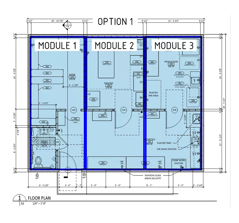
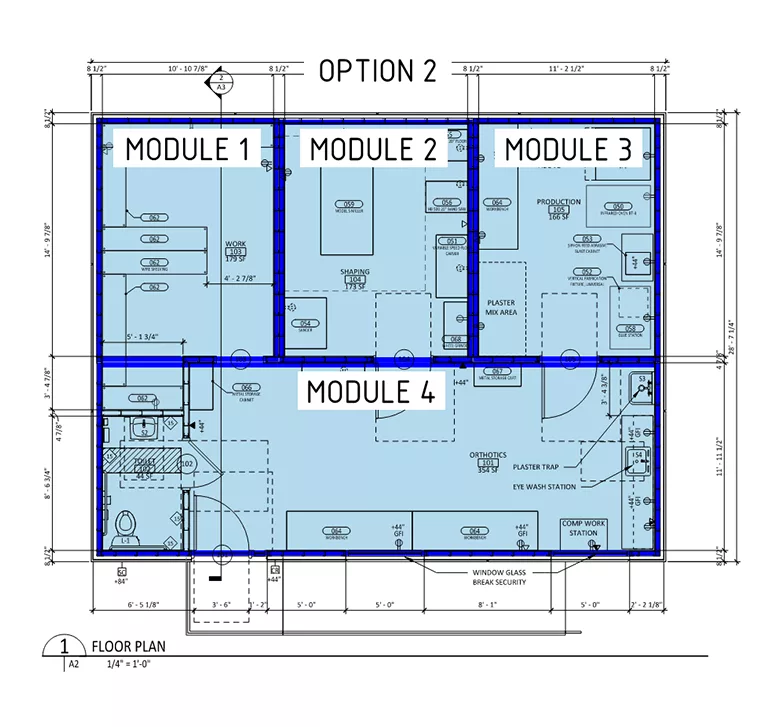
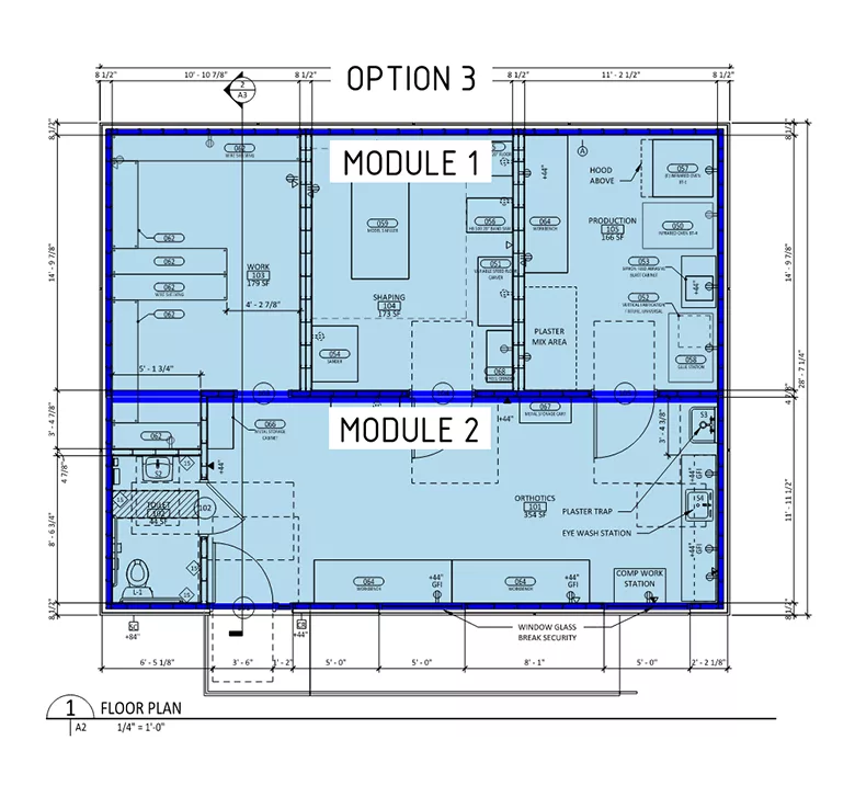
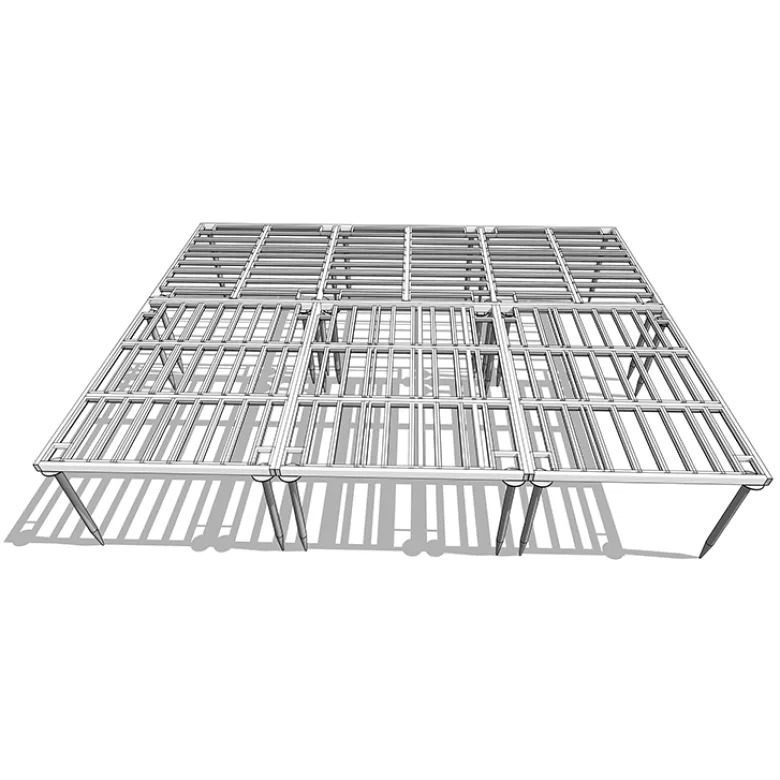
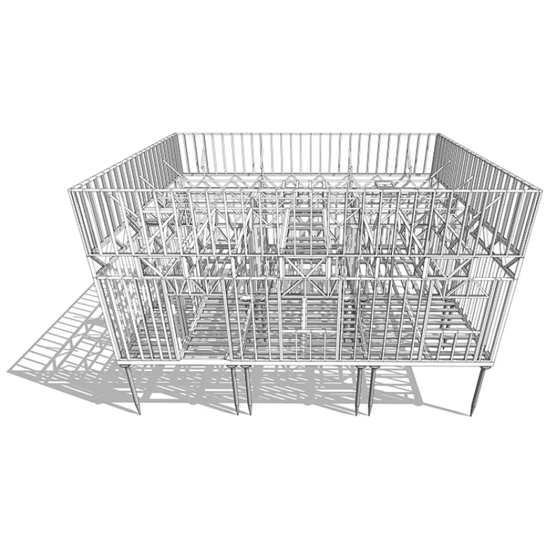
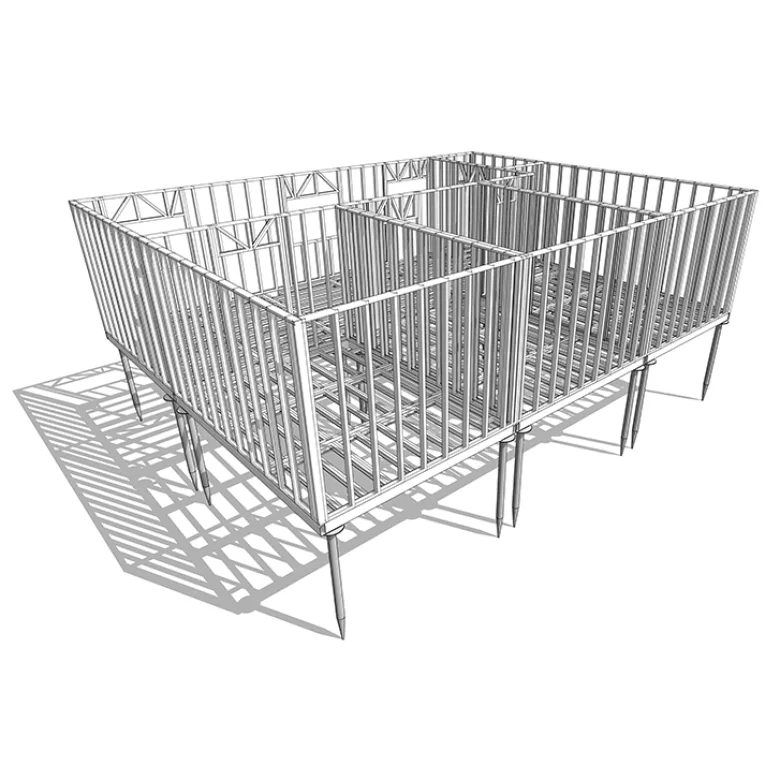
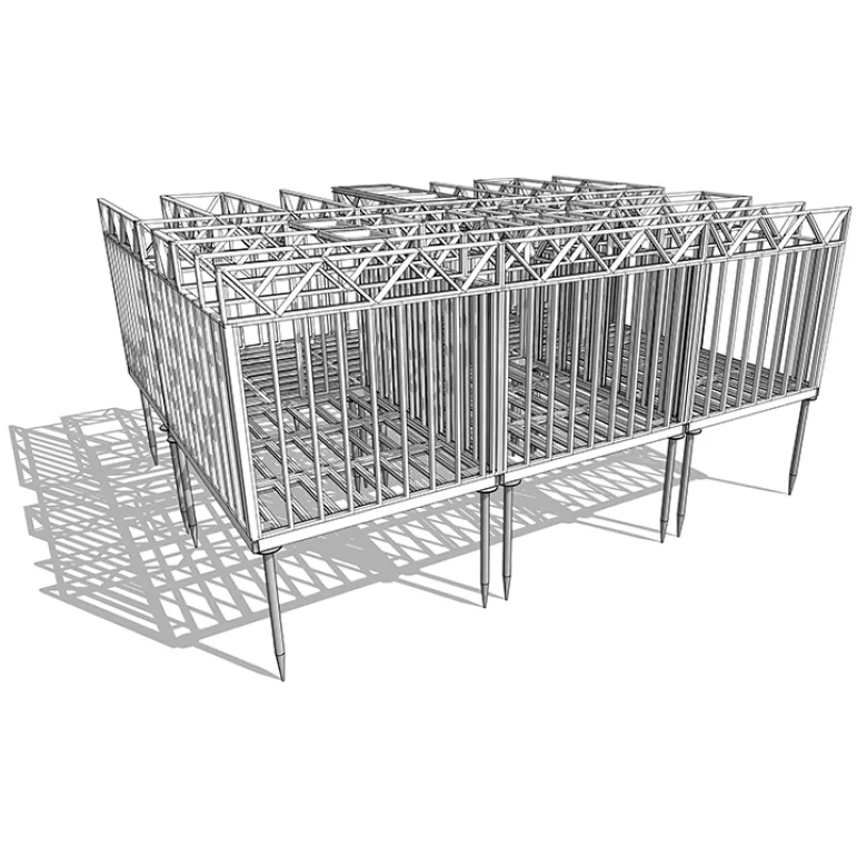
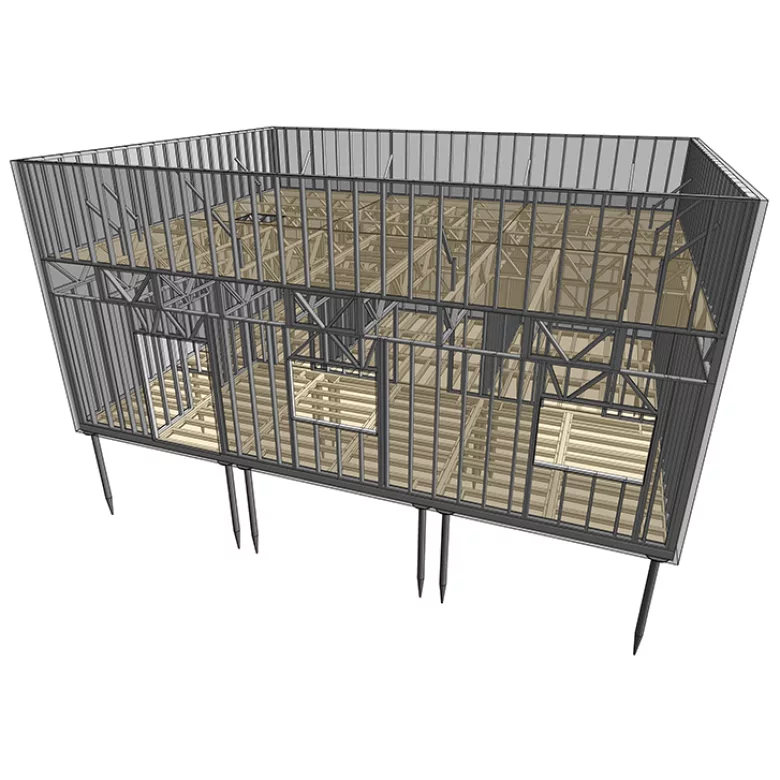
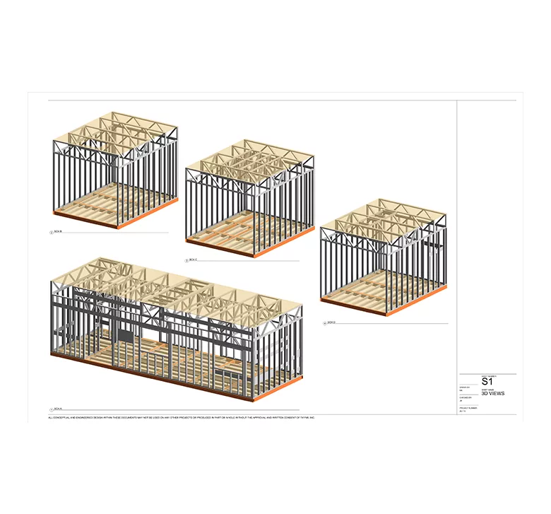
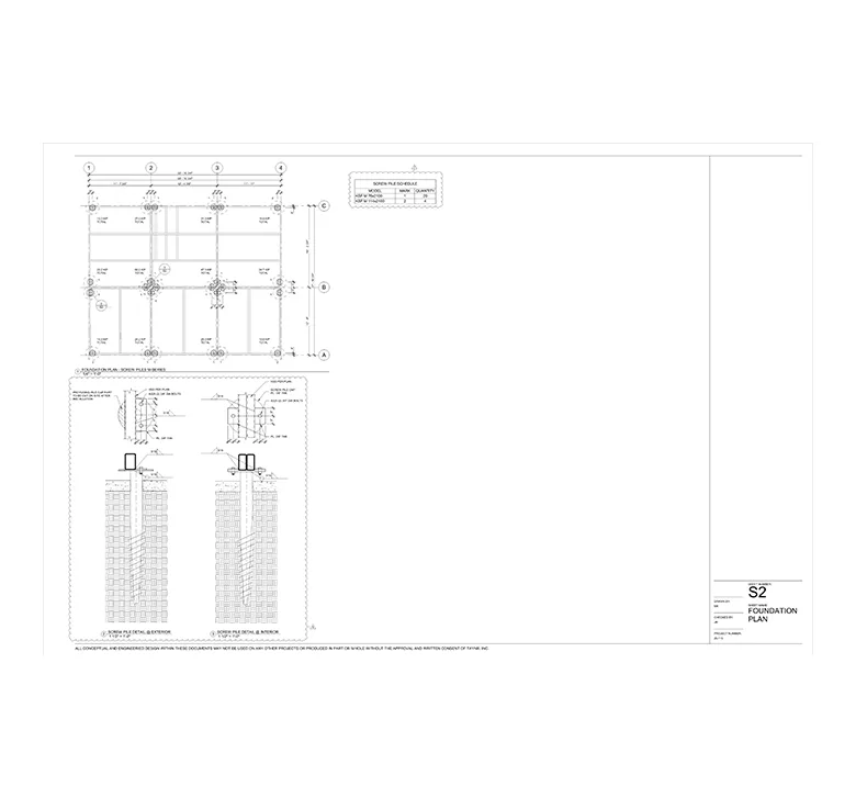
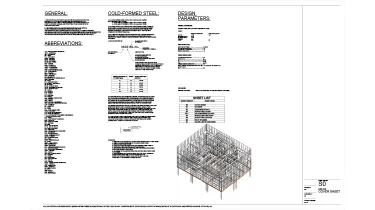
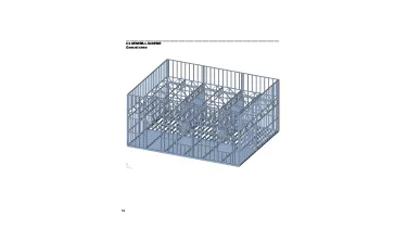
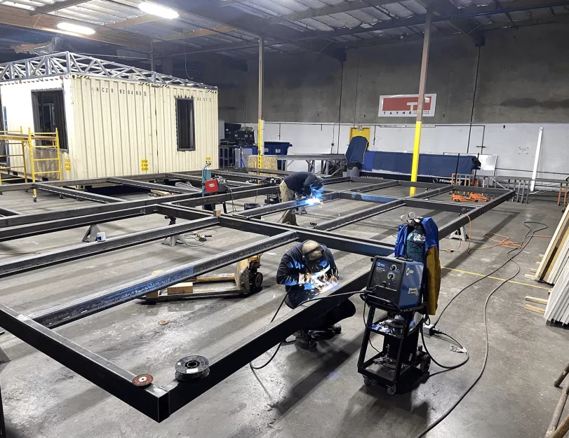
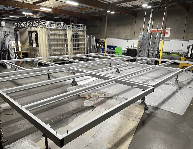
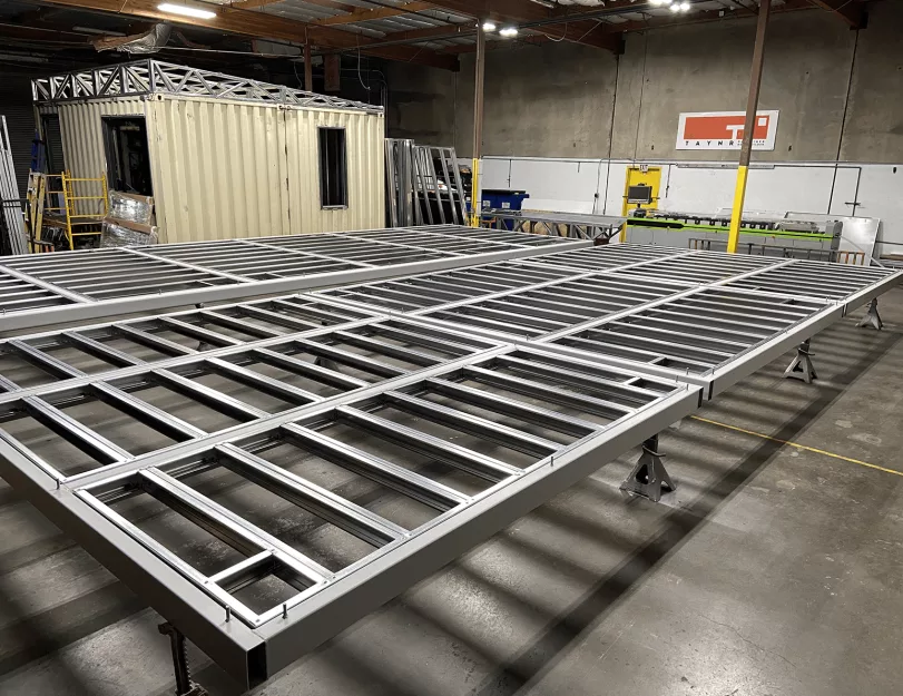
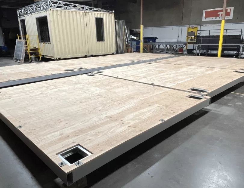
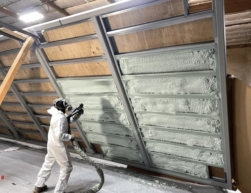
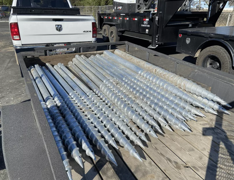
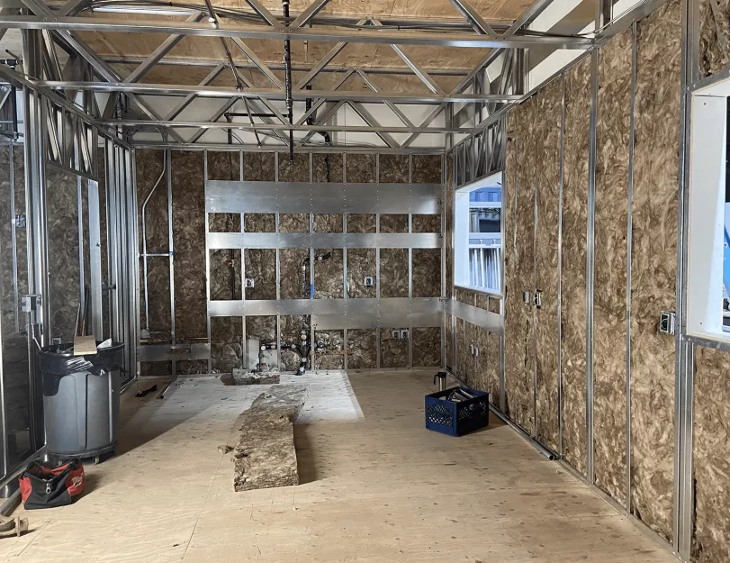
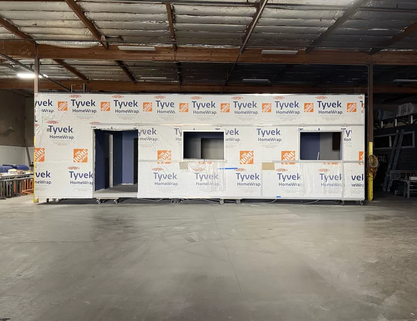
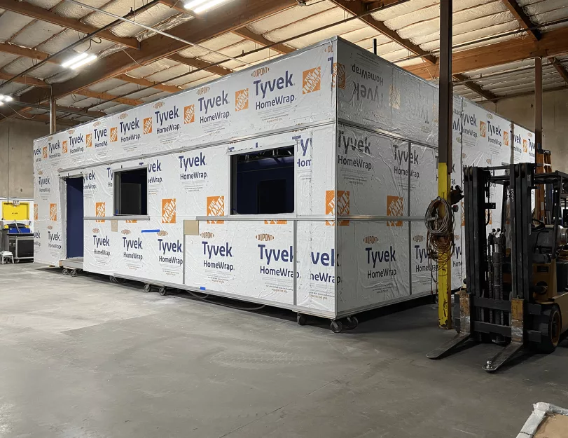
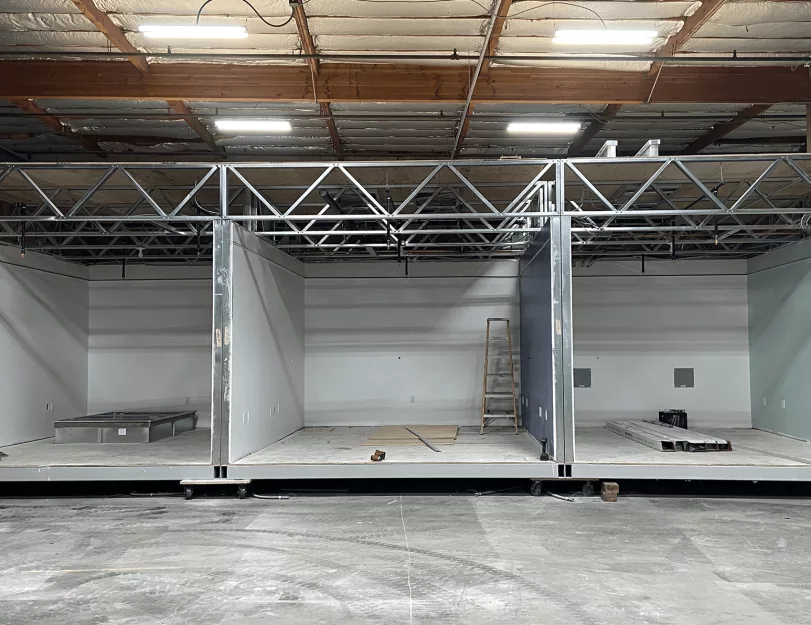
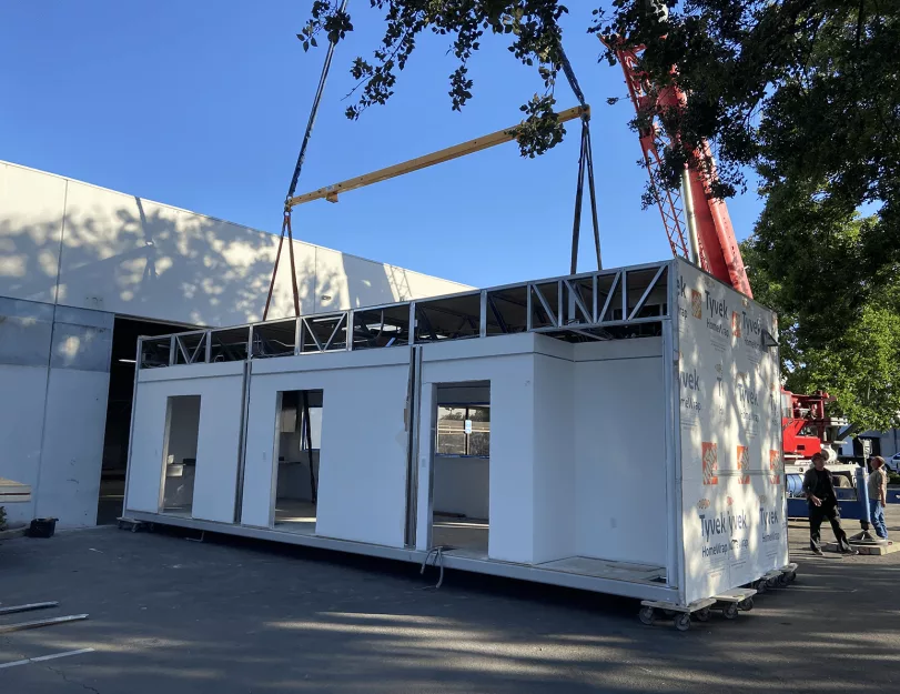
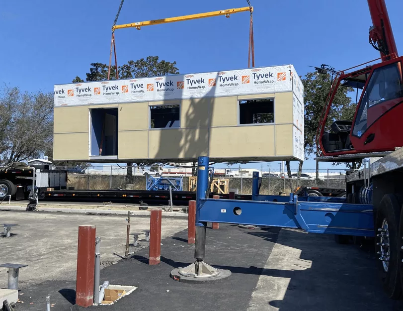
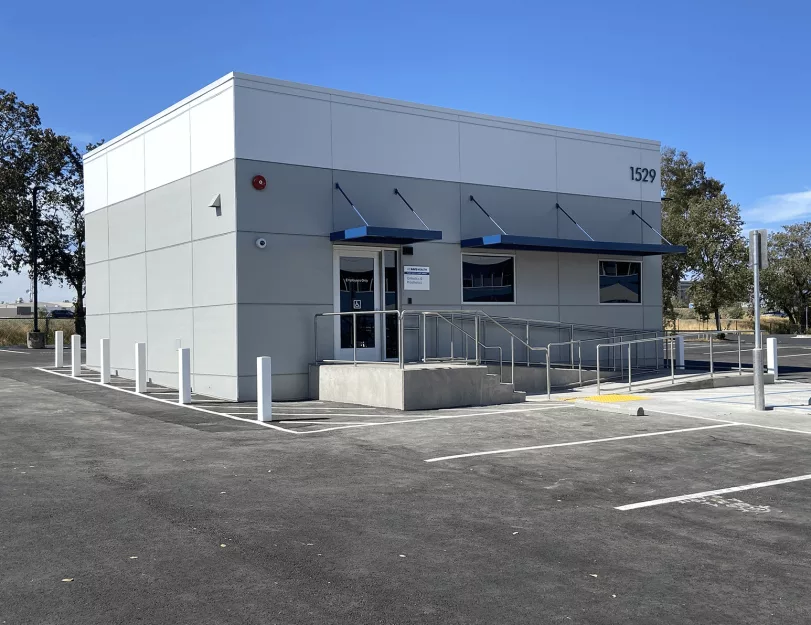
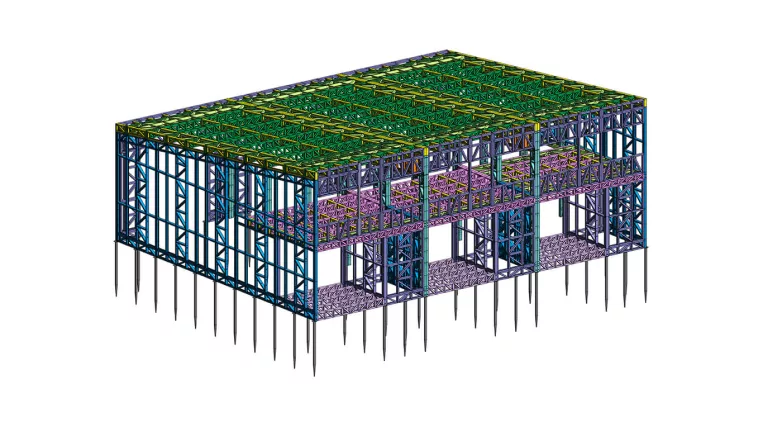
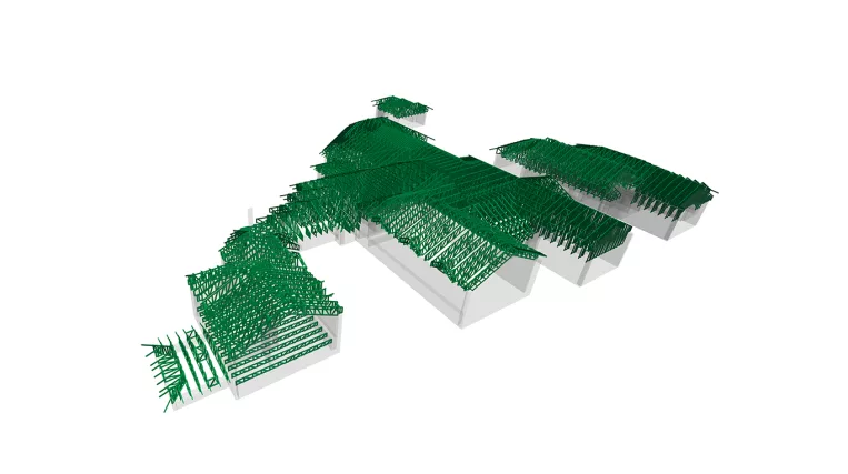
This project is a workshop for a medical hospital. A notable feature of this building is that it is prefabricated. Comprising four modules constructed off-site and delivered to the location, this construction method was chosen by the owner to reduce noise levels near the hospital. Additionally, geoscrews were selected as the foundation method to minimize on-site construction time. The use of geoscrews enables the completion of foundation work within a day.

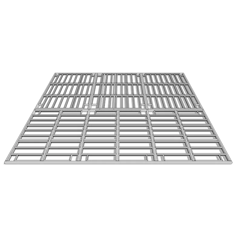
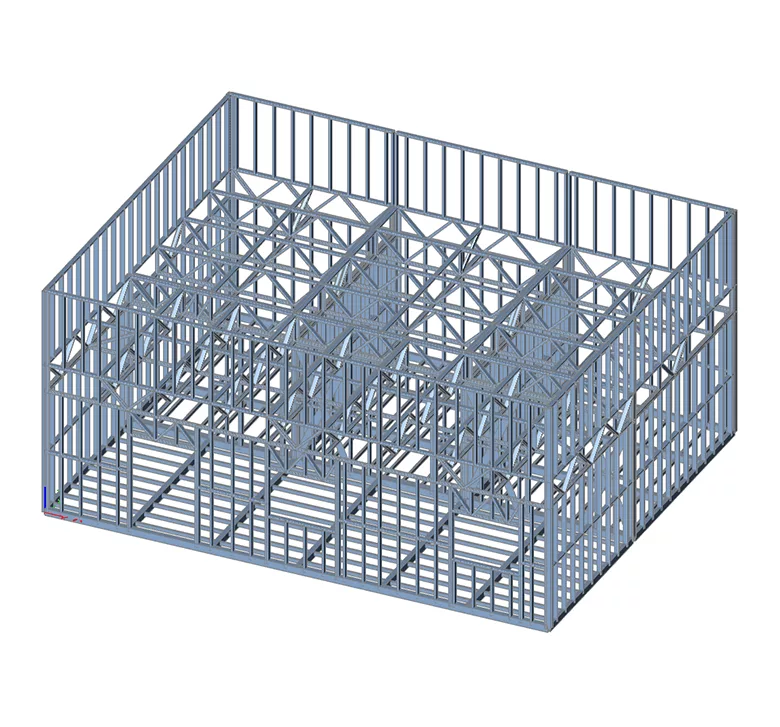
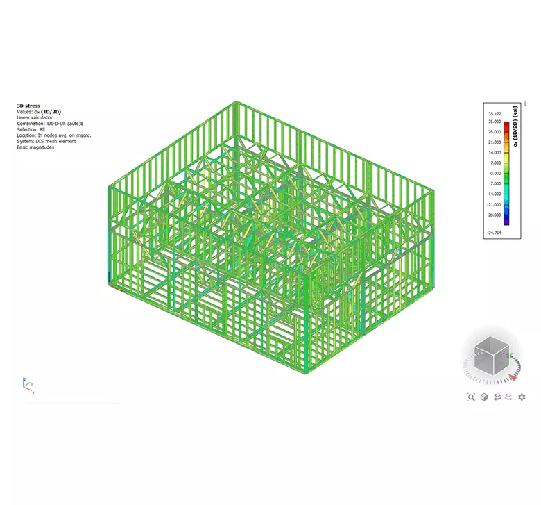
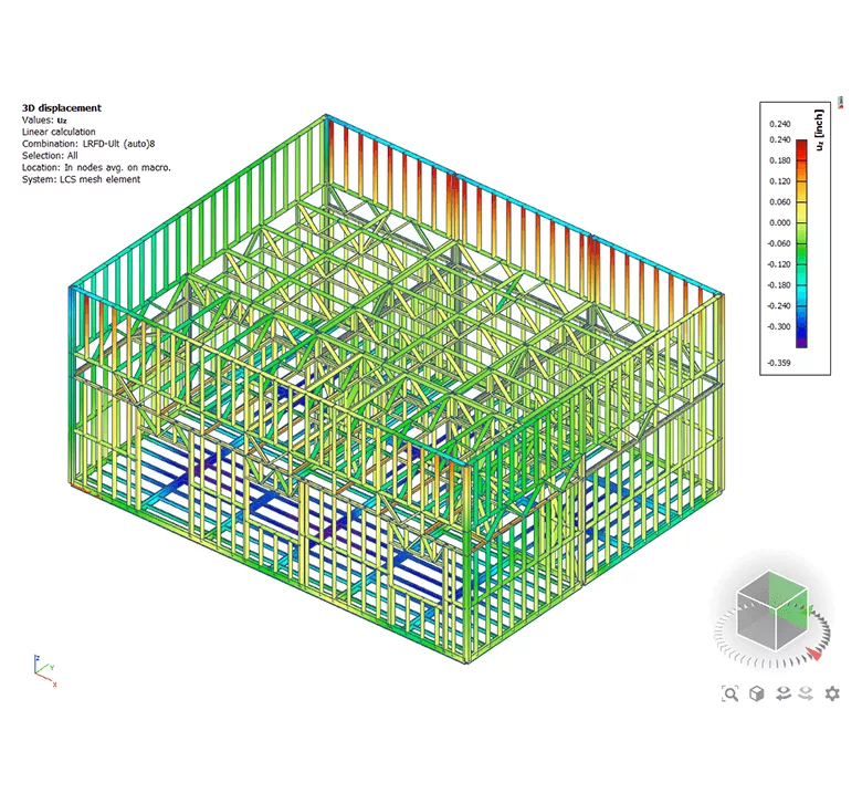
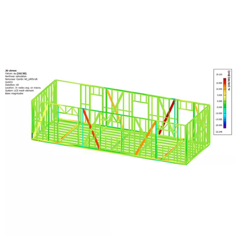
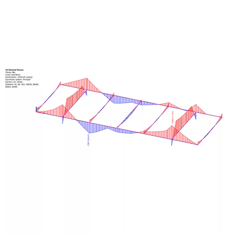
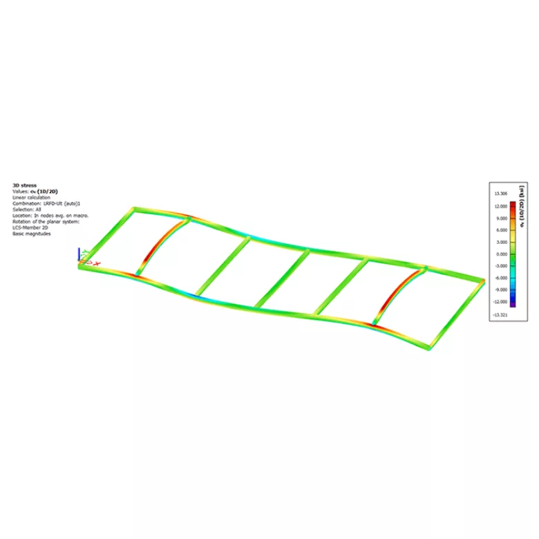
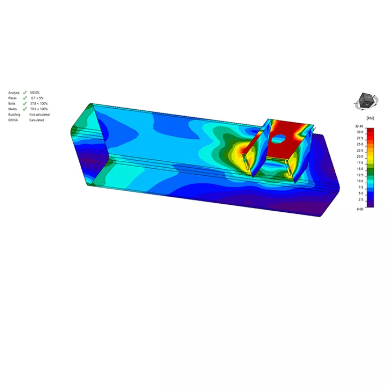
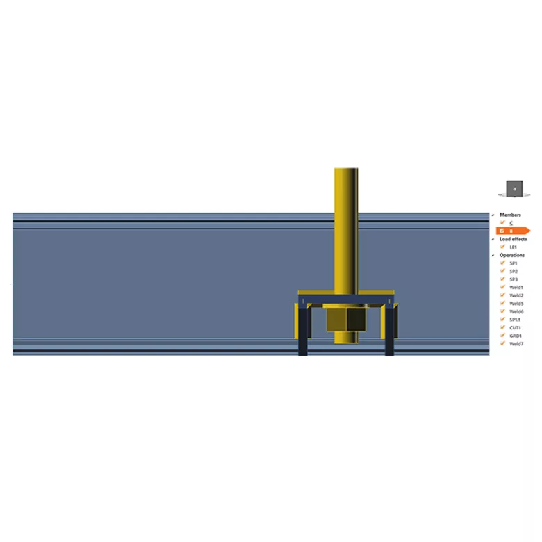
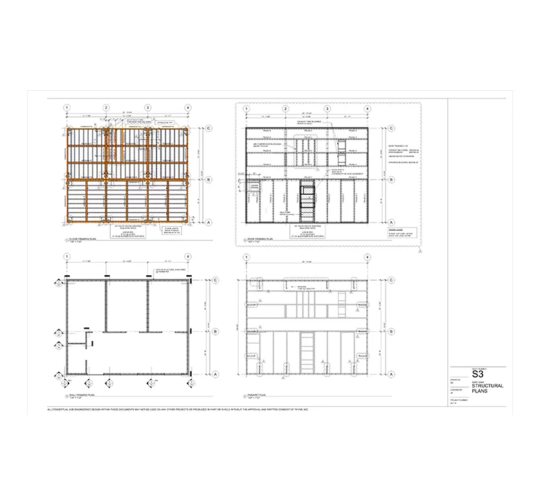
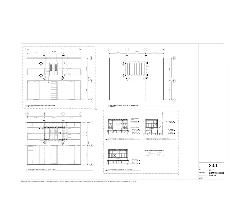
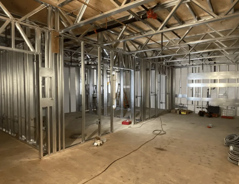
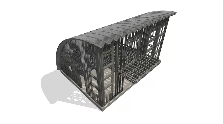
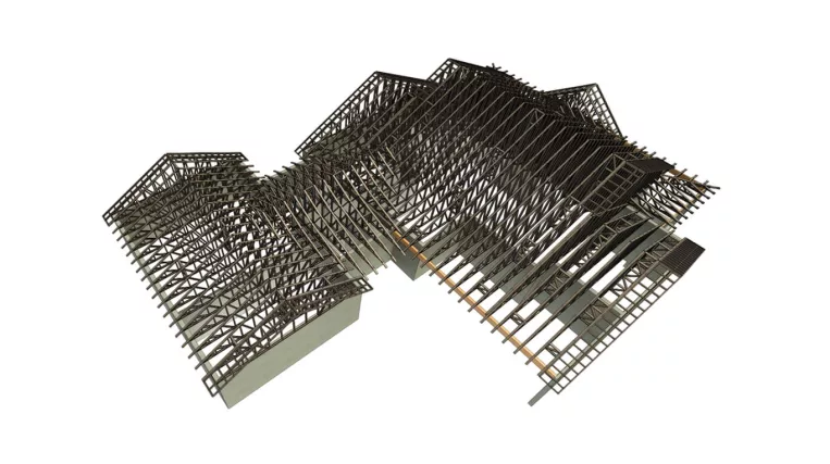
ORIGIN has been commissioned to develop structural construction drawings and perform structural analysis of the LGS framing and foundation of the building.

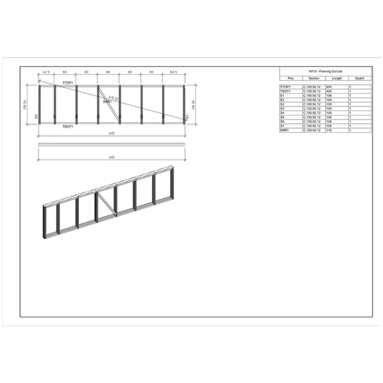
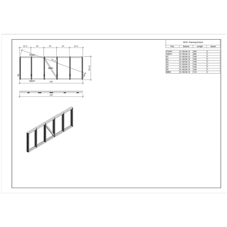
Since the project’s builder owns a Framecad rollformer, CNC files for LGS panel production were also required.

Input: Architectural drawing set.

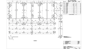
Project Deliverables:

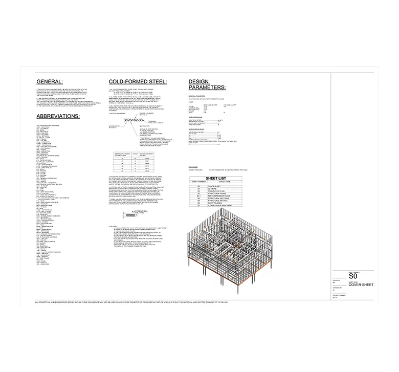
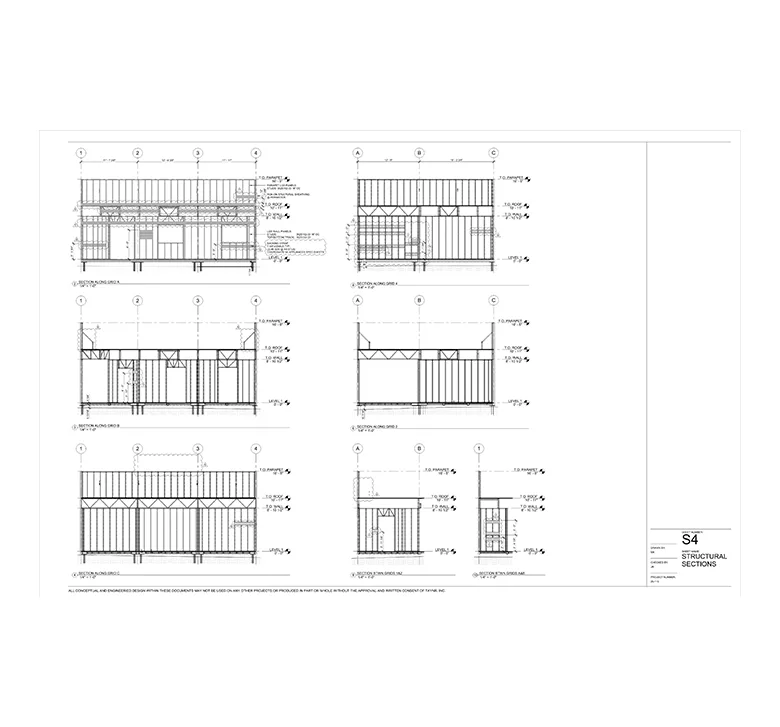
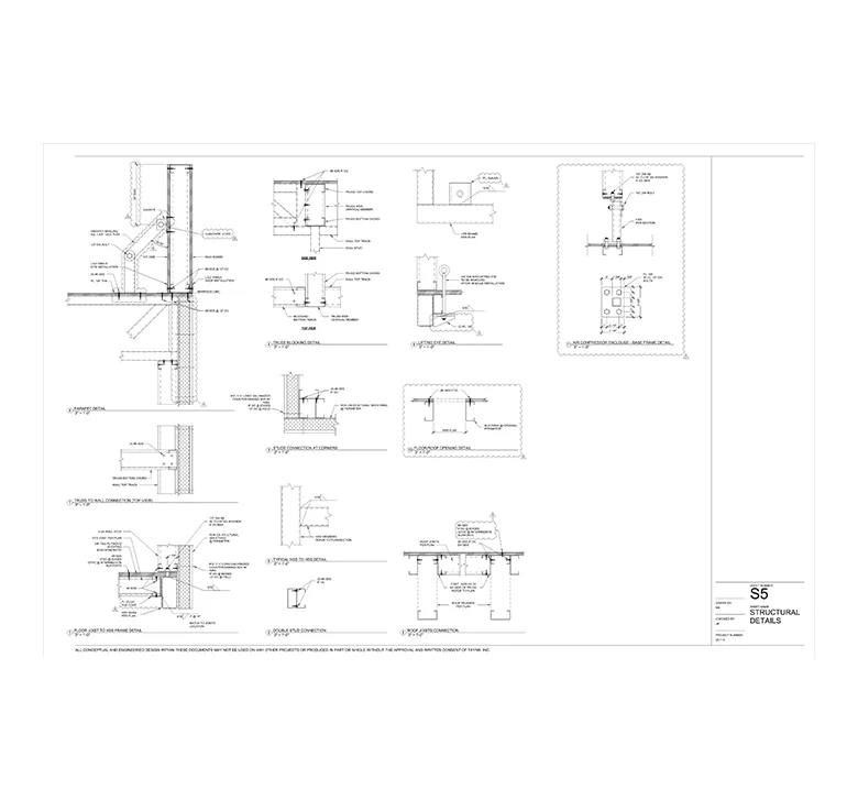
  • Structural drawing set;
  • Structural analysis report;
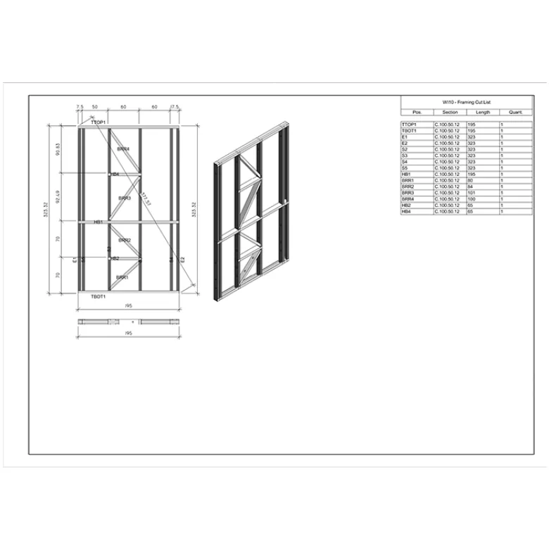
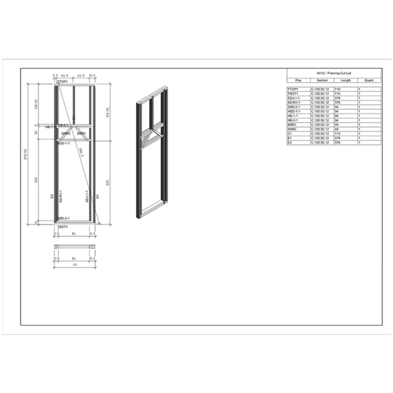
  • LGS shop drawings;
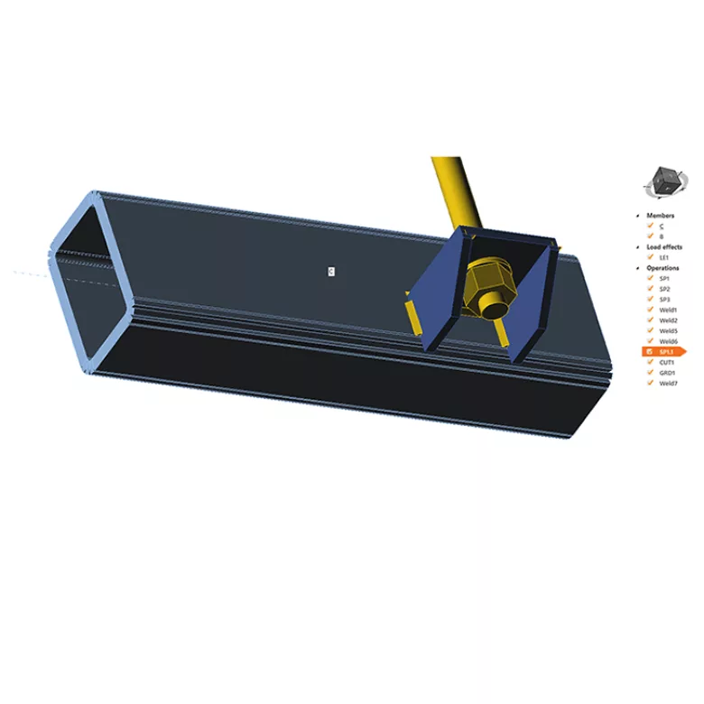
  • Hot-rolled shop drawings;
  • Framecad CNC files for LGS panel production.
Services: STRUCTURE
Subservices: Light gauge steel design and detailing
Industry: Healthcare
Object type: Hospitals
Area: 90 m² / 970 ft²
Tools used: Autodesk Revit, Strucsoft MWF Advanced Metal, SCIA Engineer, Tekla Tedds
Share:
Project stages
1. Module Layout
2. Steel Framing Design
3. Structural Analysis
4. Structural Drawings
5. LGS CNC Export and Shop Drawings
Code/Authority List:
  • 2019 California Residential Code (CRC);
  • 2019 California Building Code (CBC);
  • ASCE 7-16 Minimum Design Loads and Associated Criteria for Buildings and Other Structures.
1
1
1

Step 1 — Module Layout

In prefabricated buildings, efficient module layout is crucial. Each module must fit within transportation limits and should be designed to minimize visible joints. We start with a review of the architectural floor plans, redlining them and selecting a few options for the module layout. Preliminary calculations are then performed to ensure the layout is structurally sound.

Step 2 — Steel Framing Design

Once the module layout is finalized, we begin the steel framing design. We use HSS profiles to create a flat frame, which is then filled in with LGS framing. This design provides the necessary strength and rigidity for shipping and placement over geoscrews.

1
1
1
1
1
1
1
1
1

Step 3 — Structural Analysis

After completing the preliminary structural modeling, we begin the structural analysis of the entire structure. Calculations for steel framing are performed using SCIA Engineer software, and IDEA StatiCa software is used for connections analysis.

Our calculations comply with the following codes:

  • 2019 Edition of the International Building Code;
  • 2019 Edition of the International Residential Code;
  • ASCE 7-16 Minimum Design Loads and Associated Criteria for Buildings and Other Structures.

At the end of this page, you will find a comprehensive structural analysis report.

Additionally, separate calculations are also provided to ensure the module can withstand the loads that occur during its placement by a crane. We perform calculations to confirm that the frame is strong enough to be lifted in the air by just four points. The lifting connection is calculated using IDEA StatiCa software.

1
1
1
1
1
1
1
1
1
1
1
1
1
1

Step 4 — Structural Drawings

With the steel framing verified through calculations, we begin to prepare Revit views, including plans, sections, elevations, and details. Since we have a completed structural model, the drawing production becomes straightforward, requiring only dimensions, text annotations, and notes. Completed plans are then sent to the building department for approval.

Step 5 — LGS CNC Export and Shop Drawings

Once the plans are approved, the final step is steel structure production. Hot-rolled steel frame detailing drawings are produced using Tekla Structures software. For LGS framing, we provide CNC files for the Framecad rollformer, as well as panel assembly drawings.

1
1
1
1
Drawings

Click on preview to view high resolution PDF drawings

Construction process
Benefits

The BIM model has become an industry standard, especially for prefabricated homes. It enables clear understanding of the module’s volumetric size, which is vital for shipping. It also allows for clash detection, preventing costly issues on the construction site, and facilitates the issuance of accurate construction drawings.

Tools used
1
Autodesk Revit
1
Strucsoft MWF Advanced Metal
1
SCIA Engineer
1
Tekla Tedds
view project view more view photos