Search...
Overview

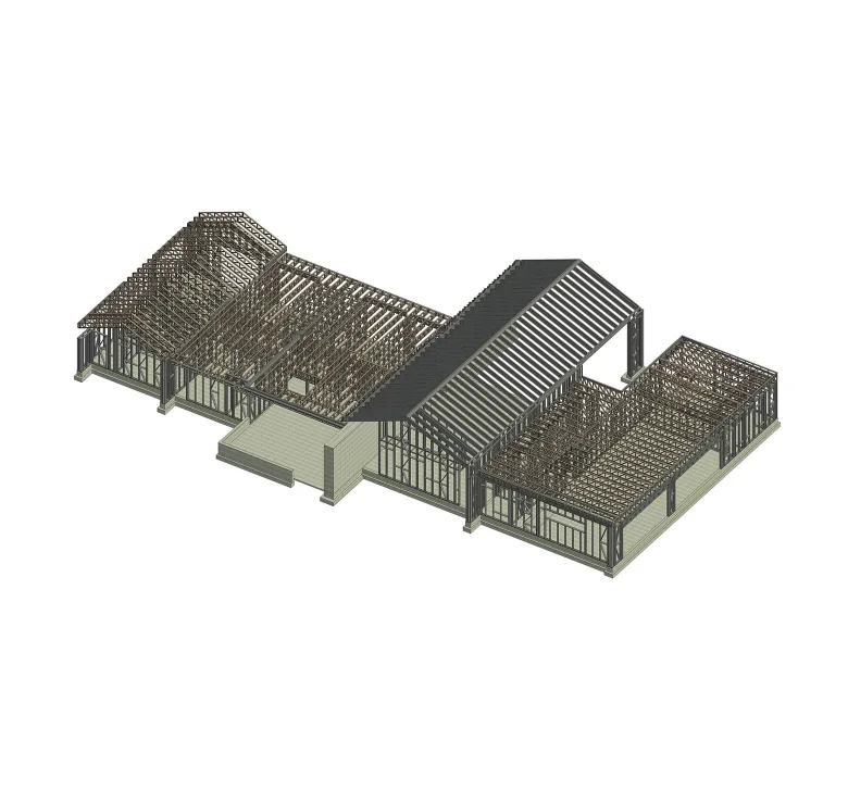
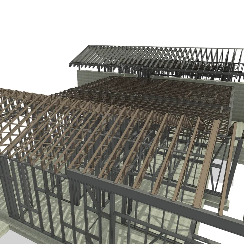
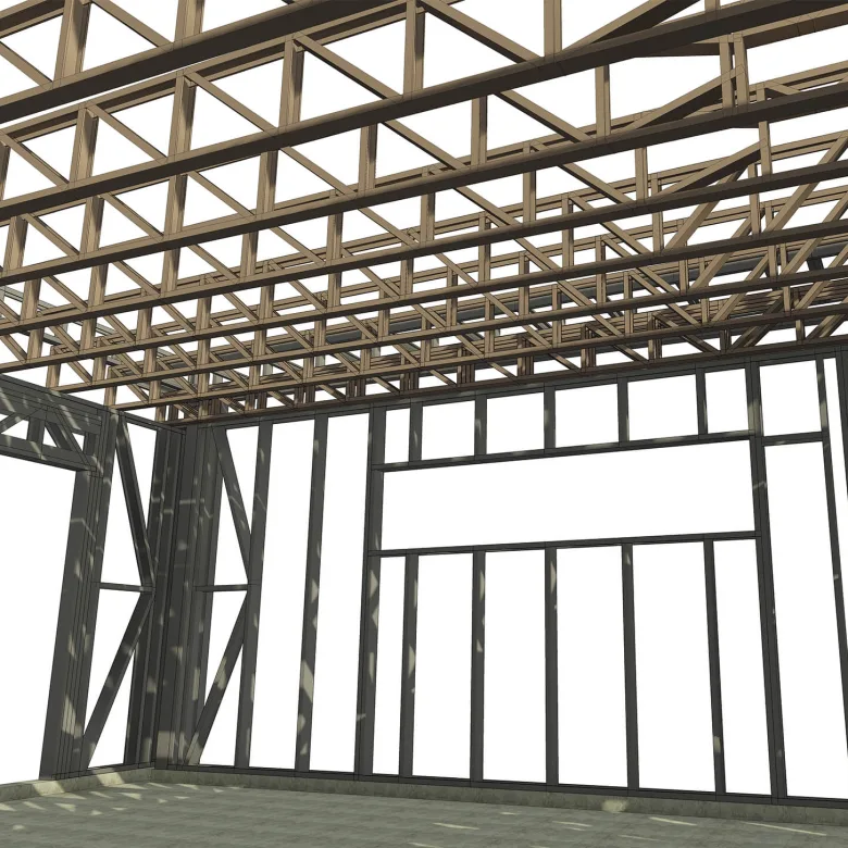
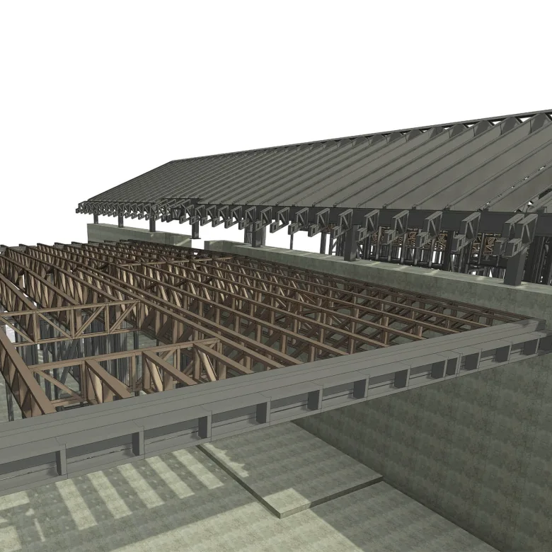
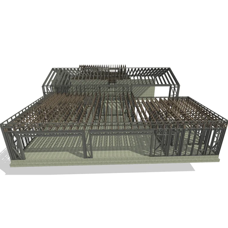
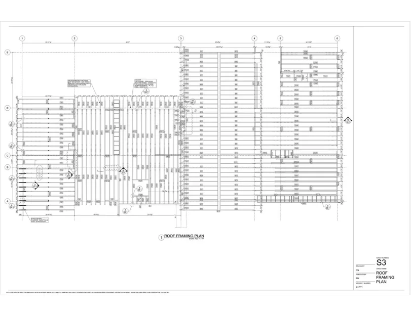
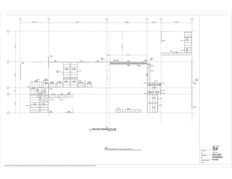
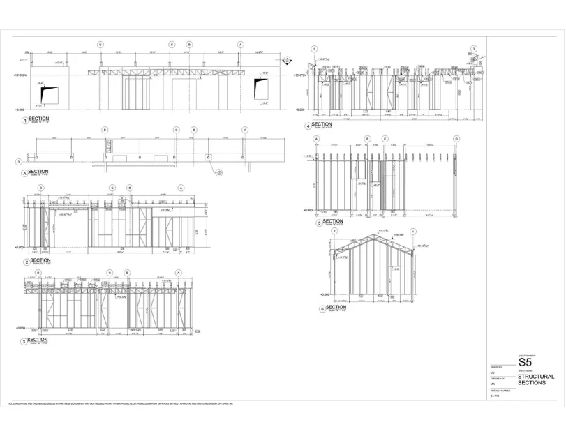
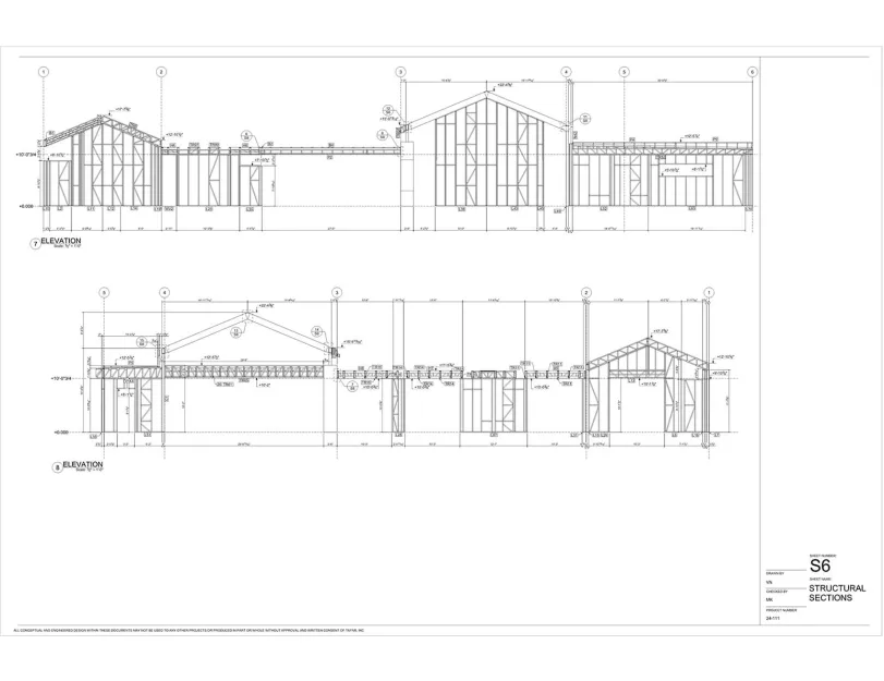
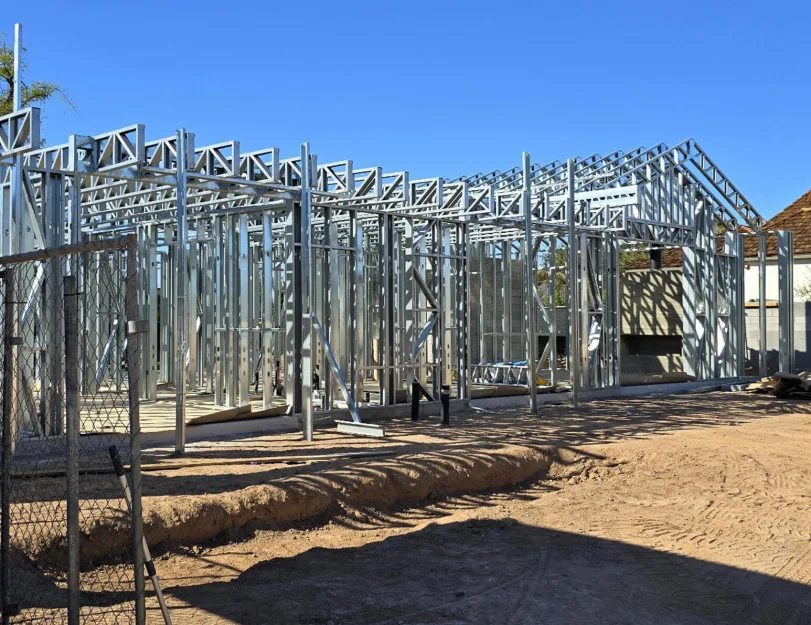
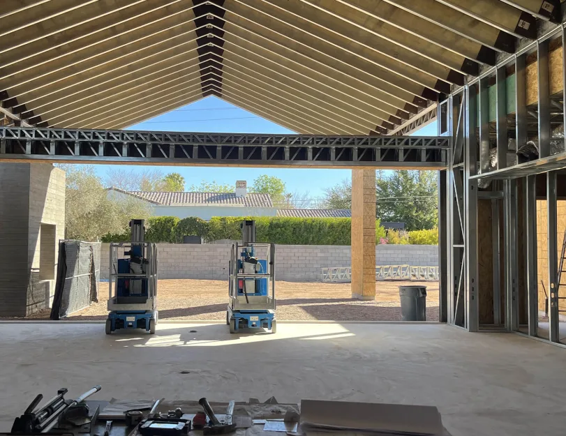
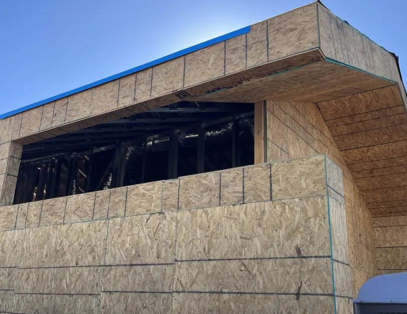
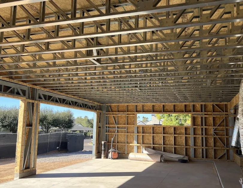
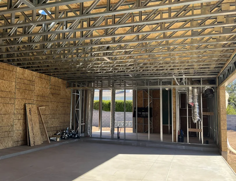
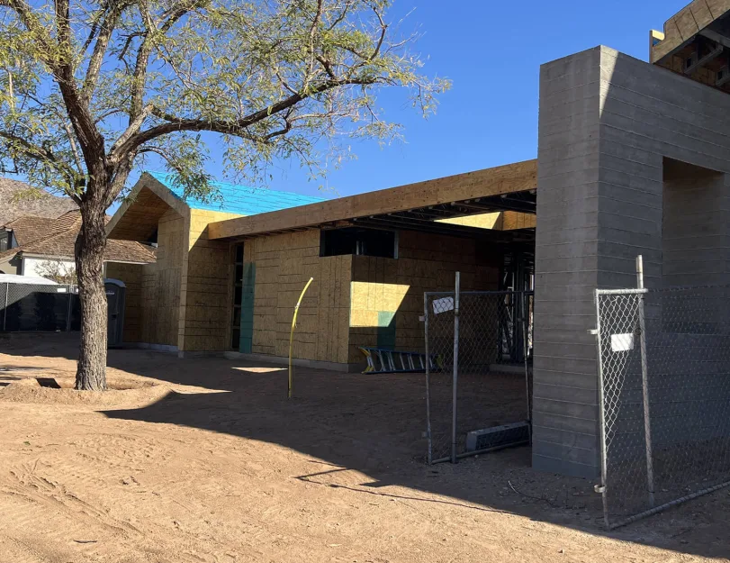
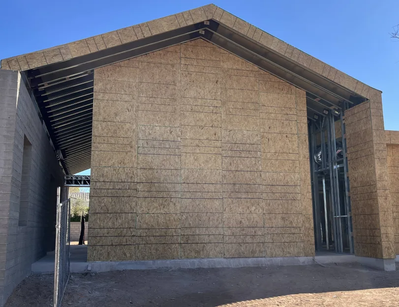
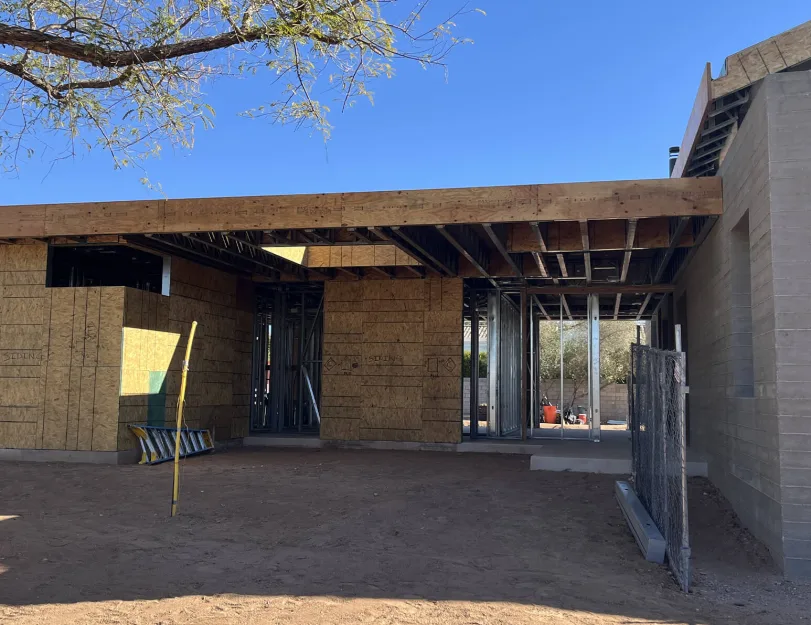
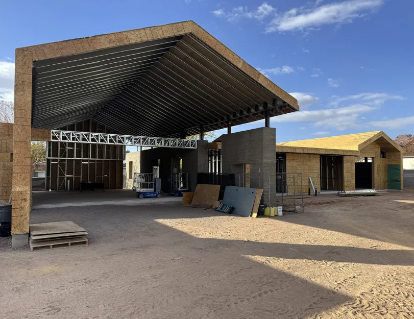
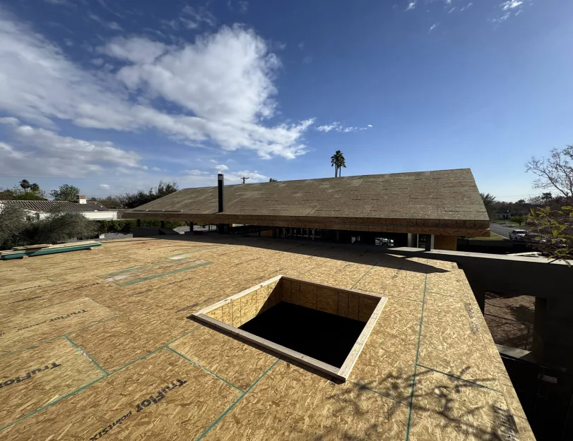
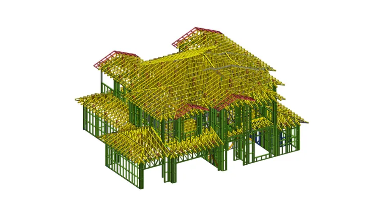
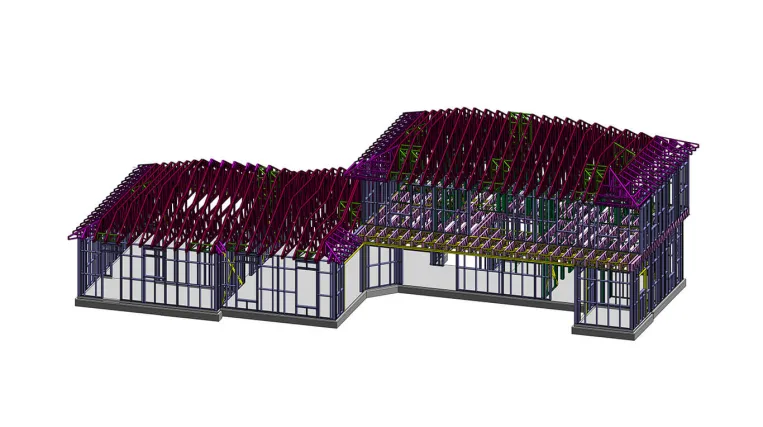
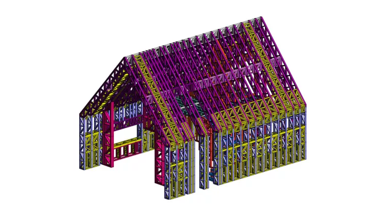
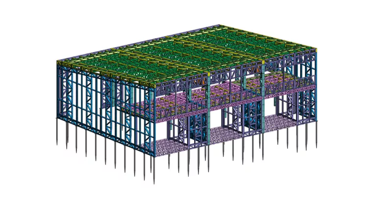
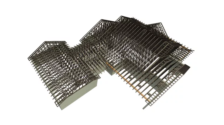
The project features a one-story residential building with a uniquely complex and spacious floor plan, measuring 138′-1.5″ in length and 66′-3″ in width. As part of the scope, the ORIGIN team had to analyze the architectural drawings and deliver a comprehensive set of deliverables, ranging from structural drawings to CNC files for LGS panels production.

Input: Architectural drawings set

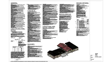
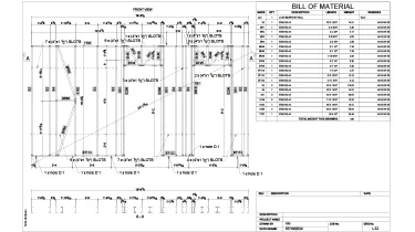
Project deliverables:

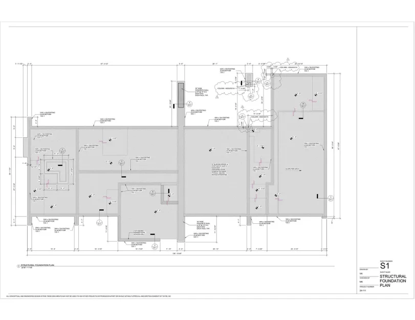
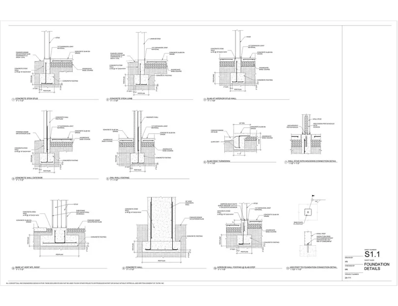
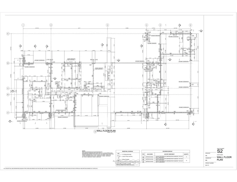
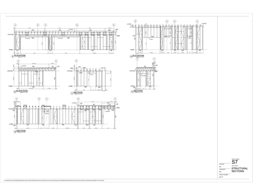
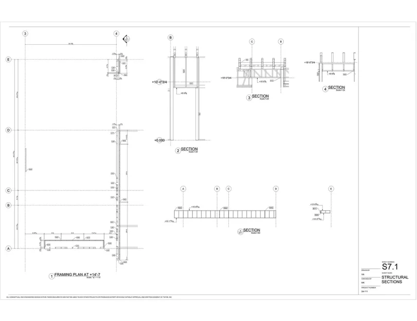
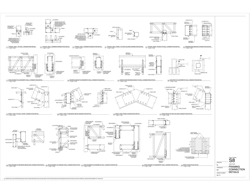
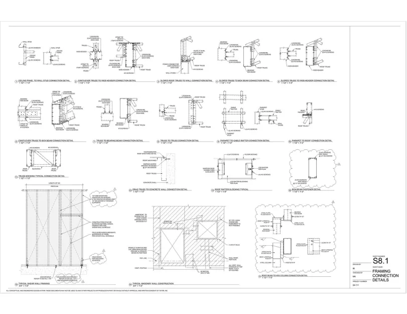
  • Structural drawings set;
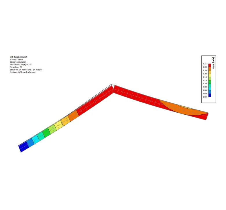
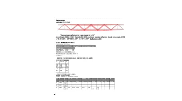
  • Structural analysis report;
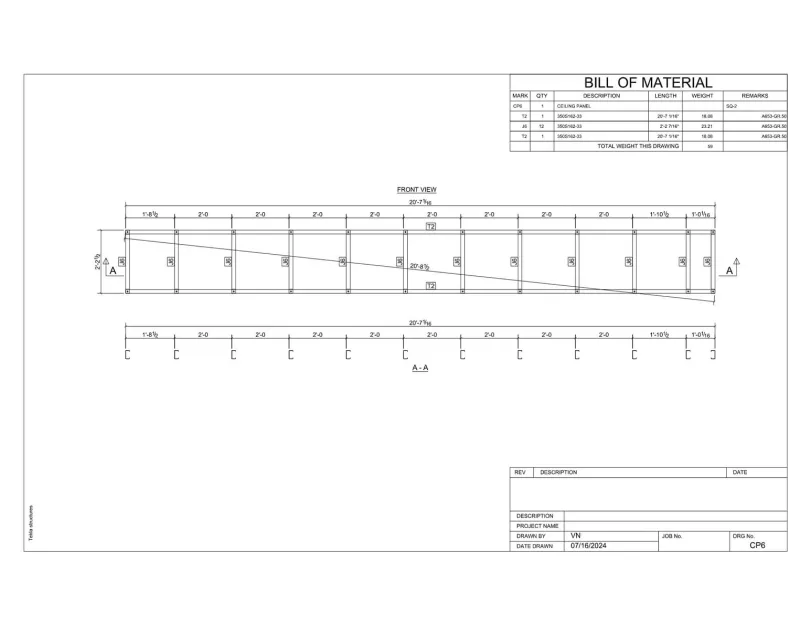
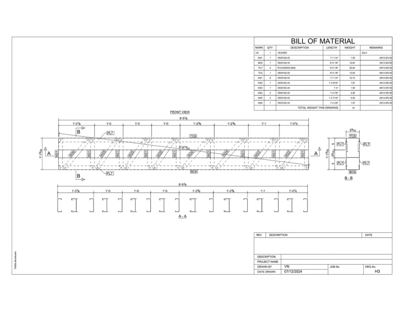
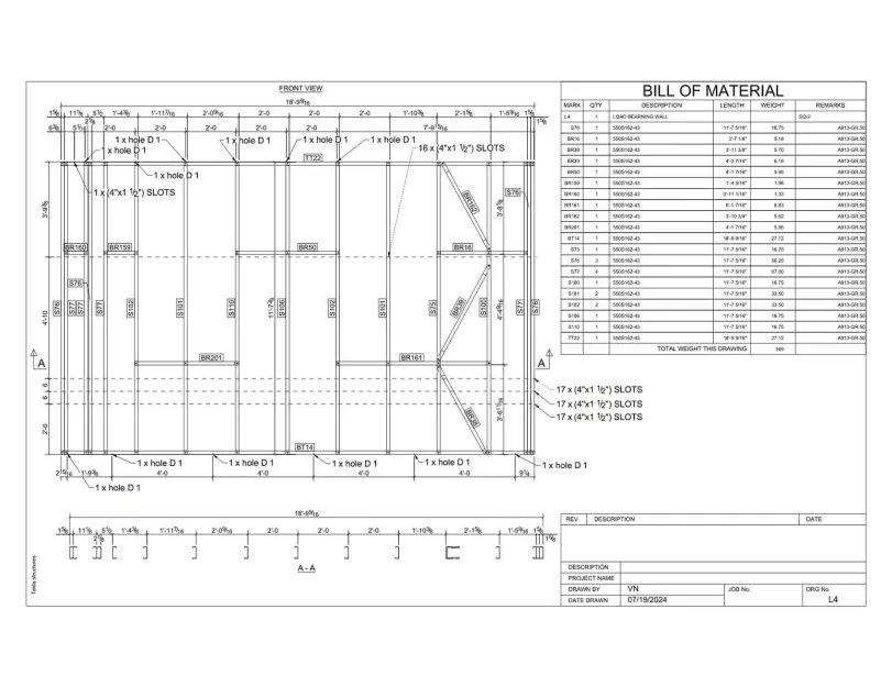
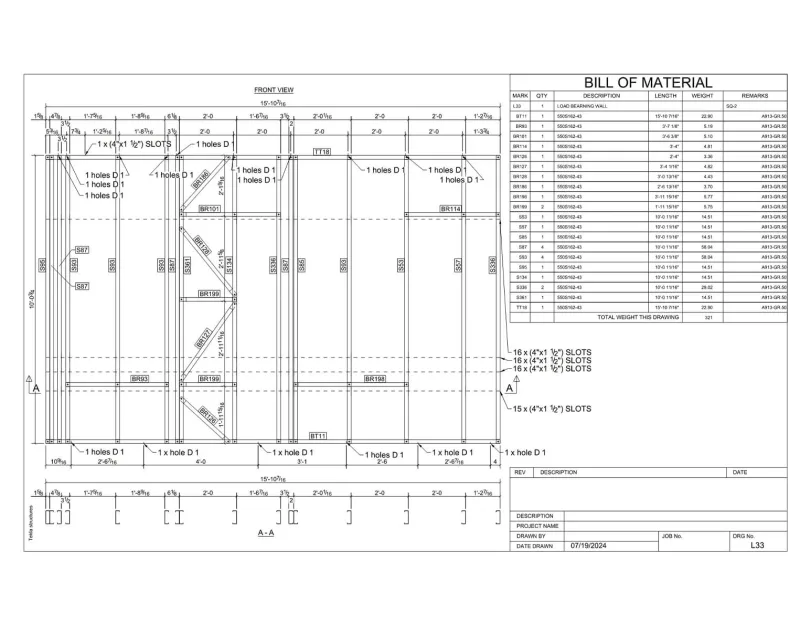
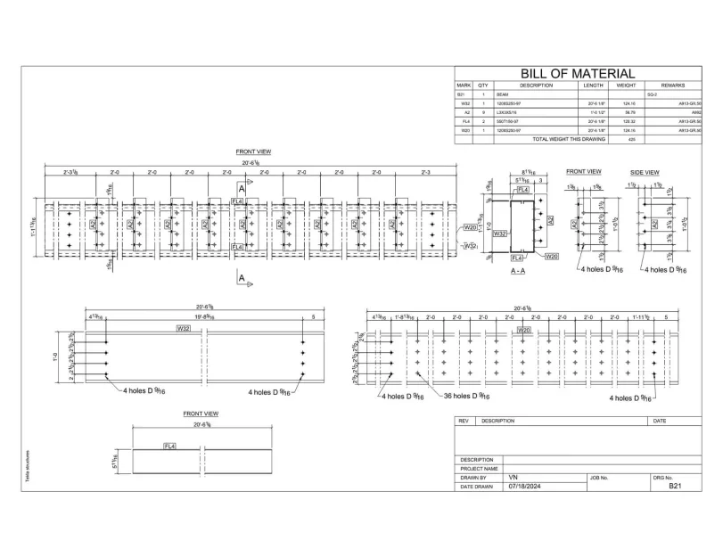
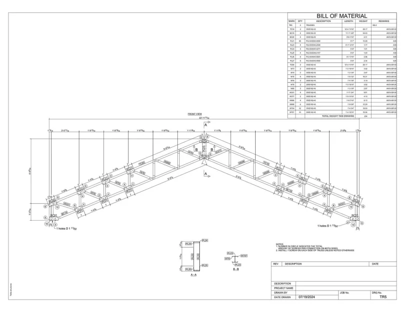
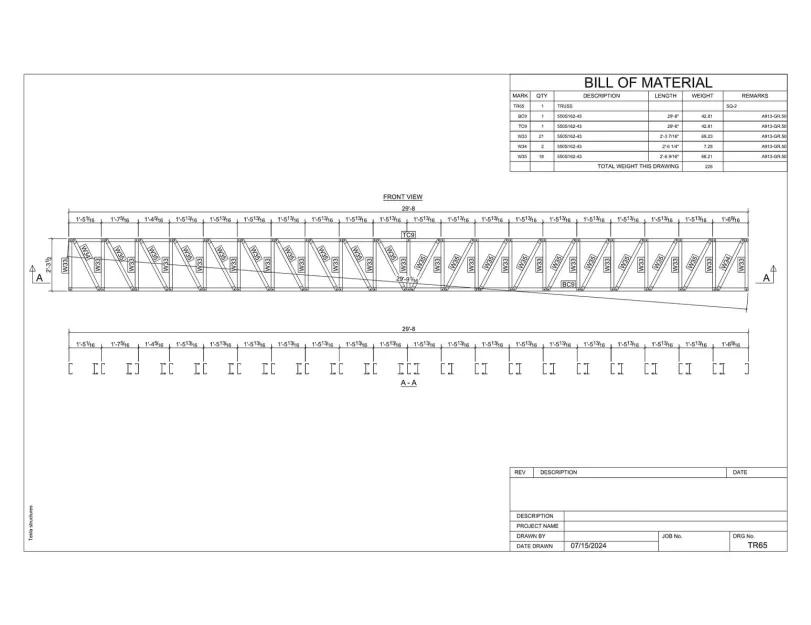
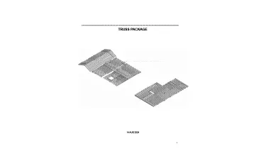
  • LGS and hot-rolled steel shop drawings;
  • CNC files for LGS panels production.
Category: STRUCTURE
Services:Hot-rolled steel design and detailing, Construction drawings, Prefabricated construction services, LGSF design and detailing, Hot-rolled steel framing, Cold-formed steel framing, Fabrication/Installation drawings, Concrete foundations, Wood framing
Industry:Residential
Object type:Single-family home
Area:653 m² / 7030 ft²
Tools used:Autodesk Revit, Strucsoft MWF Advanced Metal, SCIA Engineer, Tekla Tedds, Tekla Structures
Share:
Project stages
1. Revit model creation
2. Structural modeling
3. Structural analysis
4. Structural drawings creation
5. CNC files and shop drawings
Code/Authority List:
  • Phoenix building code (IBC 2018 with amendments and additions);
  • 2018 Edition of the International Building Code;
  • ASCE 7-16;
  • Steel design: AISC 360-16: LRFD Specification for Structural Steel Buildings;
  • Cold-formed steel: AISI S100-16w;
  • Seismic AISC 341-16 Seismic Provisions for Structural Steel Buildings;
  • Concrete: Reinforced Concrete Design Handbook (ACI);
  • Ultimate Strength Design Handbook (ACI).
1

Key challenges

The building’s complex structure combined LGS framing, a central concrete wall with steel supports, shear walls for stability, and a mixed foundation of slab-on-grade with pad footings to handle concentrated loads.

To handle the complexity, the ORIGIN team had to take an extremely structured approach, breaking the project into several stages: modeling in Revit, running calculations in Scia Engineer and Mathcad, and producing CNC-ready files for fabrication.

Revit host model creation

Everything started with architectural drawings. At this stage, it was crucial to confirm the structural feasibility of architectural layouts. Therefore, having studied architectural drawings, we constructed a conceptual structural scheme, noted all issues, and addressed them to the architect for further adjustments.

Then, we turned the PDF architectural drawings into a clean Structural Revit model, which included foundations, floors, roofs, and walls. These models served as a host for future LGS framing.

Structural model creation

After creating the Revit model, we exported it to Tekla Structures. This was done to create walls and other elements framing using LGS extensions, which ensured higher precision in detailing and the ability to accommodate project-specific requirements that went beyond Revit’s native capabilities.

Once the wall and framing elements were completed in Tekla, we exported them back into Revit. This way, we were able to achieve full BIM coordination. As a final touch, we completed the LGS model by creating the roof trusses with the automation capabilities of the Strucsoft MWF plugin.

1
1
1
1
1
1
1
1
1
1
1
1
1
1
1
1

Structural calculations

Following preliminary structural modeling, we began a full structural analysis of the entire building:

  • LGS framing calculations — performed with the Scia Engineer software, which excels in advanced FEM (finite element method) analysis capabilities and precision in modeling light gauge steel behavior under various loads;
  • Masonry walls and foundation calculations — done with Excel and Mathcad spreadsheets. Using these tools allowed for flexibility in applying custom formulas, quick iterative changes, and transparent documentation of calculation methods.

For more details, a full structural report is available at the end of this page.

Structural drawings production

Once LGS framing was verified by calculations, we began preparing Revit views: plans, sections, elevations, and other essential details.

Since the structural model was already completed, there was no need to draw anything manually. Thanks to this, drawing production was the easiest part: we simply added dimensions, text annotations, and additional notes. The completed plans were sent to the building department for approval.

Structural drawings
CNC files and shop drawings production

With plans approved, we moved to the final phase: producing the LGS panels.

This process had two stages:

Step 1 — Fabricate panel members. We exported CNC files from the Tekla model, and the client loaded them into a Howick rollformer, which then rolled the profiles.

Step 2 — Assemble panels. The fabrication team assembled the LGS panels from these members using the shop drawings for each panel; each member was labeled and dimensioned.

Shop drawings
Construction site
Drawings

Click on preview to view high-resolution PDF drawings

Benefits
Ensured precise alignment of LGS framing to the building geometry, eliminating on-site installation issues
Enabled use of the LGS BIM model to run clash detection against other trades
Delivered major manufacturing time savings via CNC export from the model and CNC rollformers for LGS panel production
Tools used
1
Autodesk Revit
1
Strucsoft MWF Advanced Metal
1
SCIA Engineer
1
Tekla Tedds
1
Tekla Structures
view project view more view photos