Search...
Overview

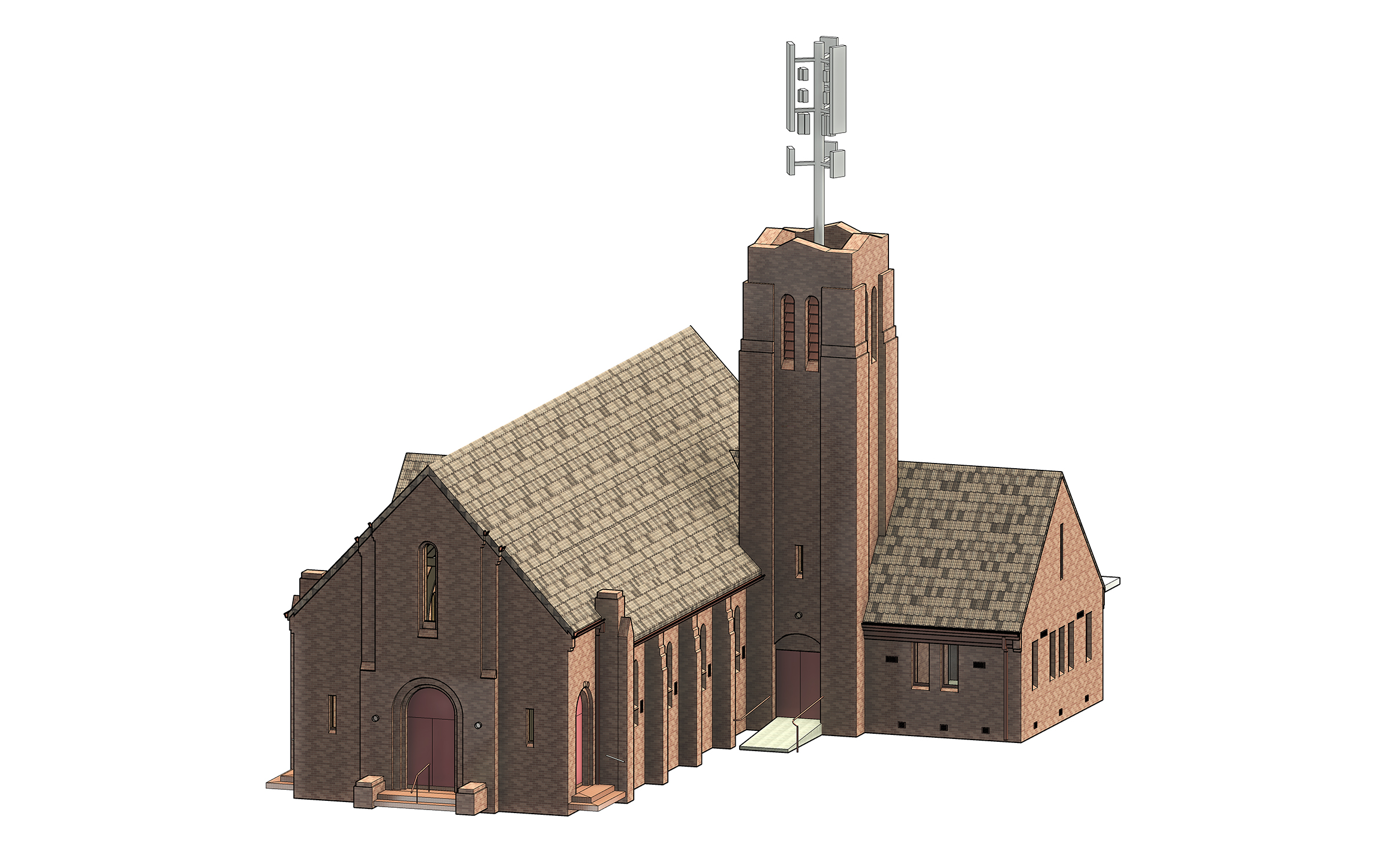
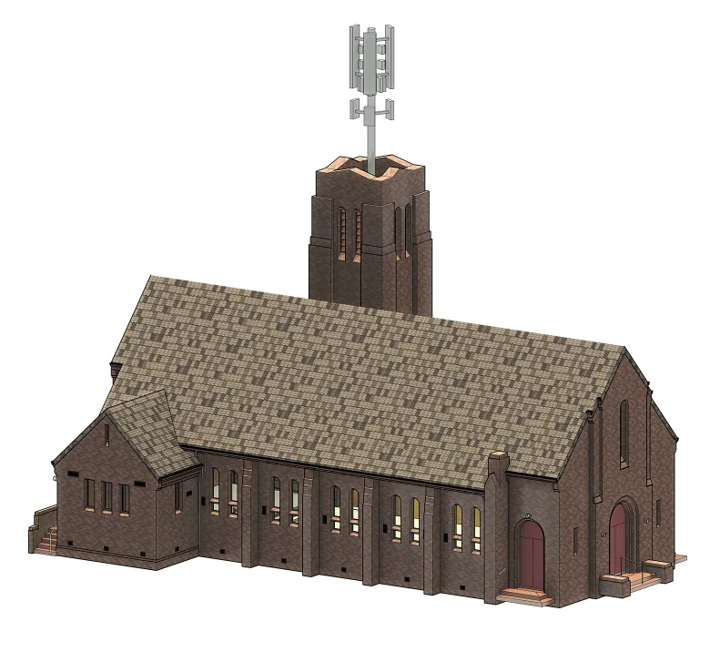
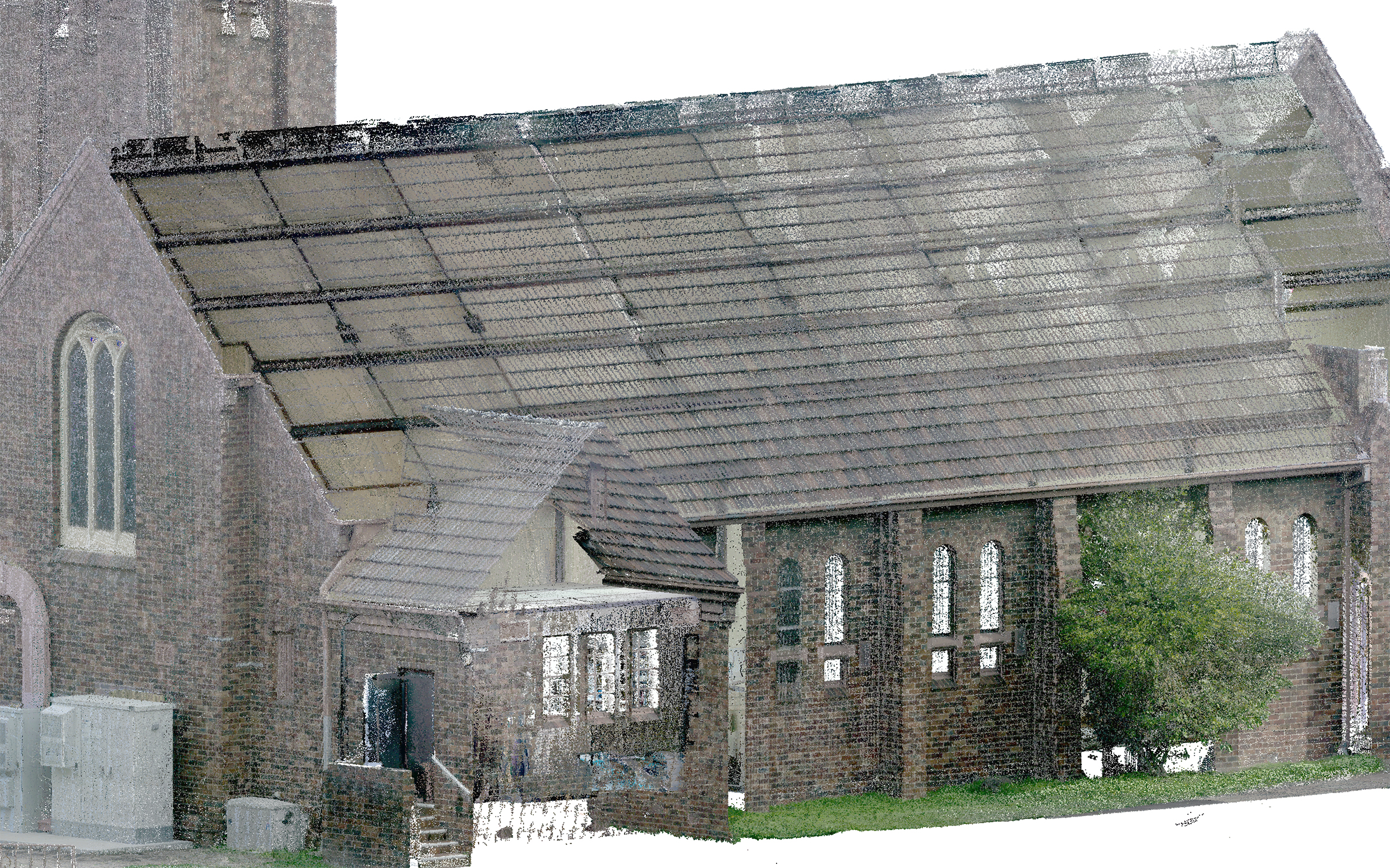
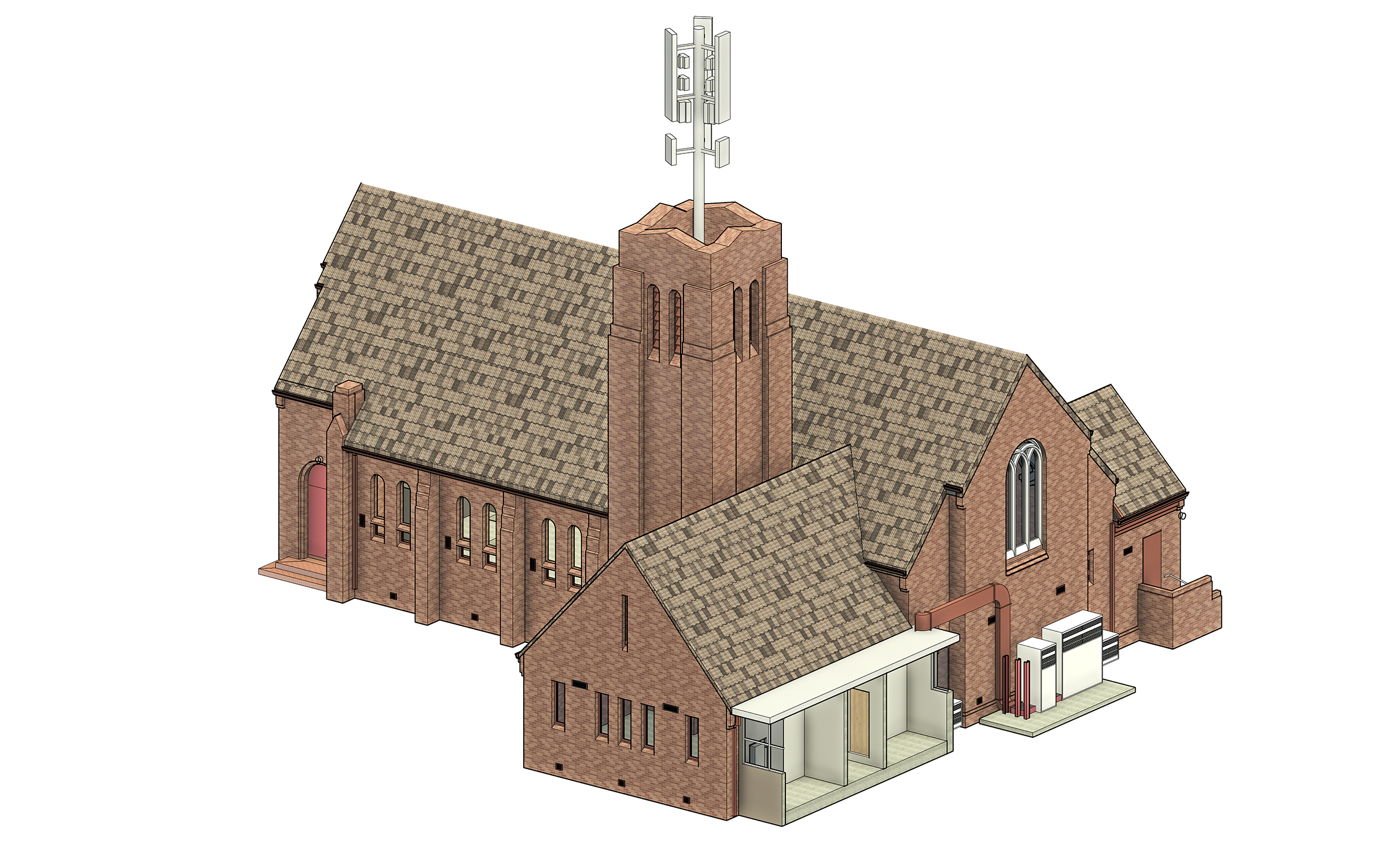
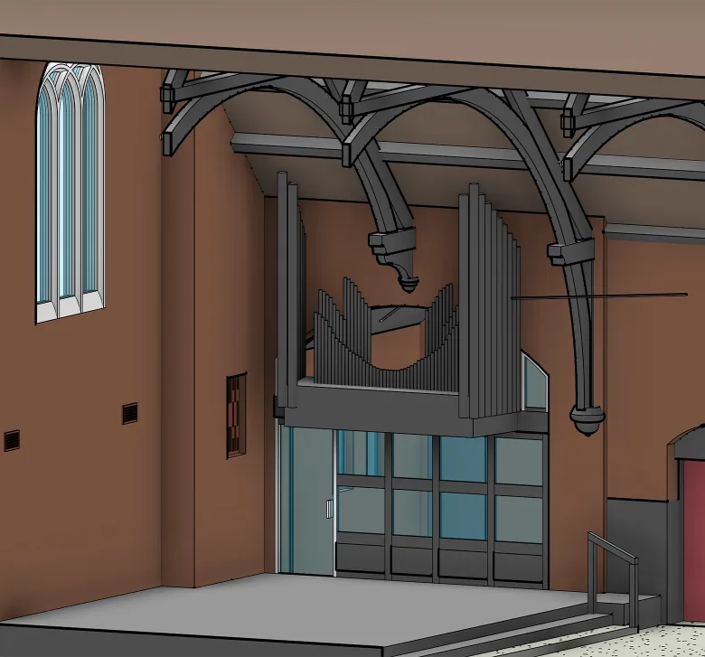
Inside the church, the as-built model shows how curved structural members support the roof and records the height and spacing of the organ pipes. Outside, it captures the brick facades, pointed-arch windows with decorative tracery, and the antenna mounted above the central tower.

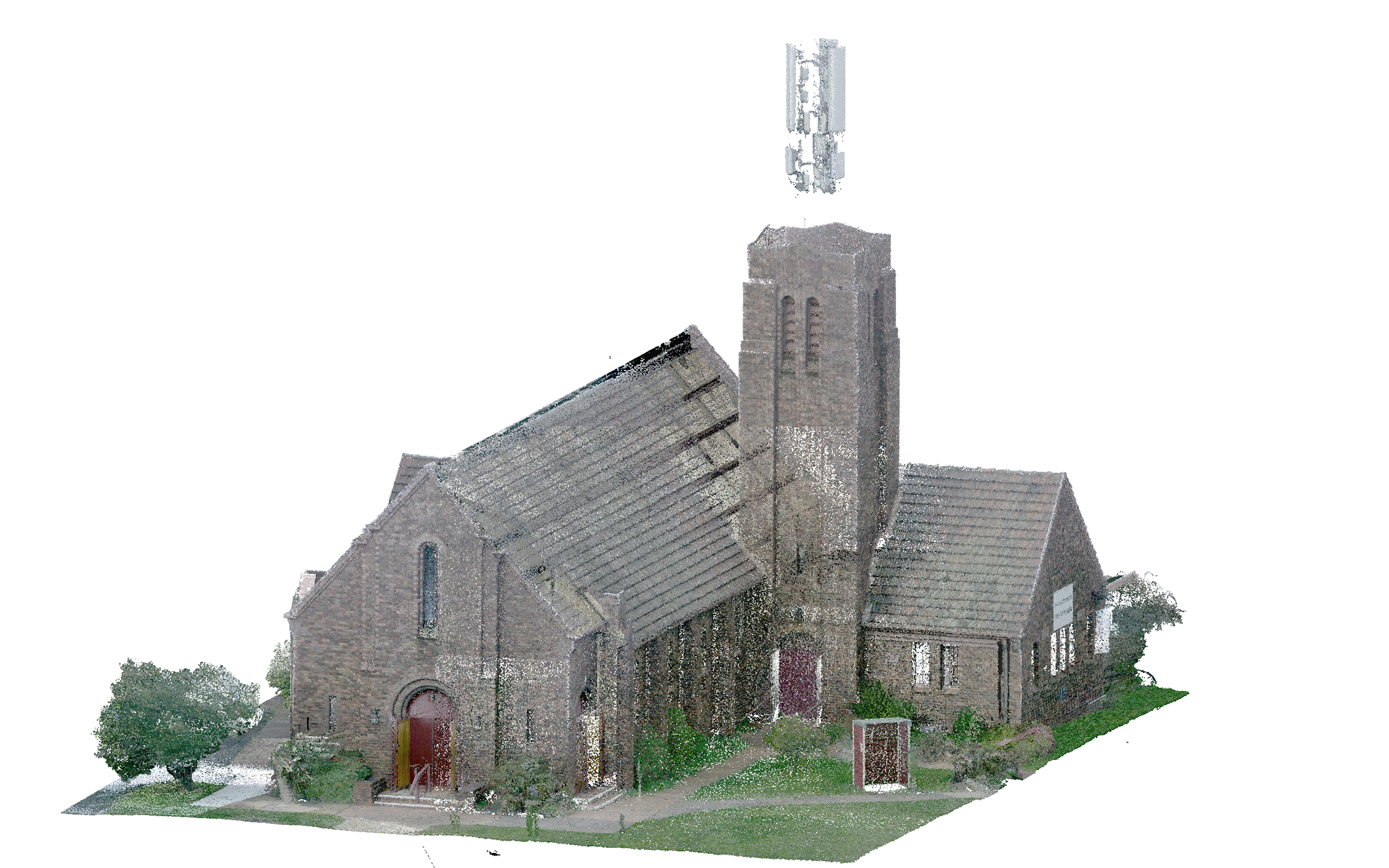
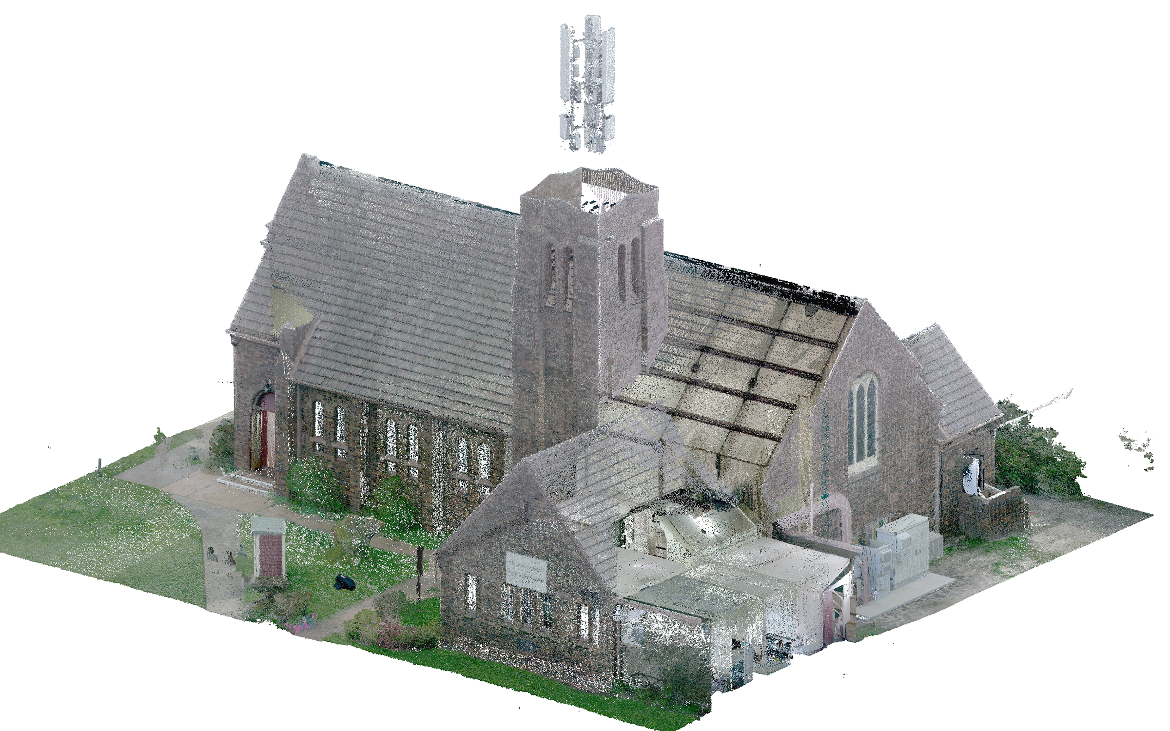
Working from point cloud data, ORIGIN developed an LOD 300 Revit model of the church and its adjacent annex. Along with the existing architecture and structure, the model includes visible exterior mechanical equipment and associated piping. Materials were assigned to interior and exterior elements to distinguish the existing finishes.

Category: BIM, STRUCTURE, ARCHITECTURE, MEP
Services:Scan-to-BIM, As-built drawings
Industry:Institutional
Object type:Churches
Area:350 m² / 3770 ft²
Tools used:Autodesk Revit, Autodesk ReCap
Share:
Project stages
1. Reviewing the client’s requirements and available reference material
2. Assessing point cloud coverage and defining the LOD 300 modeling approach
3. Modeling the exteriors of the church and annex, including brickwork, recessed openings, and arched windows with tracery
4. Modeling the central tower, antenna mast, and attached components
5. Reconstructing the roof framing, including curved supports, rafters, and connecting members
6. Modeling the pipe organ and selected interior architectural details
7. Modeling visible exterior MEP components, including HVAC equipment and associated piping
8. Assigning materials to interior and exterior elements
9. Preparing the dimensioned as-built drawing set
10. Checking the model and drawings and making final corrections
11. Delivering the LOD 300 Revit model and as-built drawings
Scope of work

Architectural and structural BIM modeling of the church and annex, including selected interior features and visible exterior MEP components, with material assignments for both interior and exterior elements.

  • Input: Point cloud data and Google Maps references.
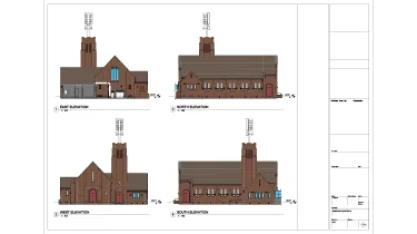
  • Output: LOD 300 Revit model and a dimensioned as-built drawing set, including elevations.
Point cloud vs model
1

Brick facades and window tracery

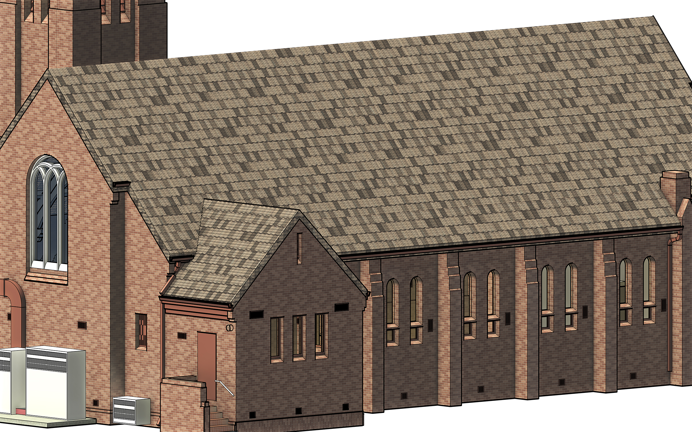
One of the church’s most distinctive windows combines a large pointed arch with curved mullions and decorative tracery. To reproduce the window as it exists today, we used the scan data to model the individual frame profiles, their intersections, and the proportions of the framing within the opening.

The brick facades also feature recessed openings, projecting vertical elements, and detailed entrance surrounds. With several window configurations and changes in facade profile across the building, the challenge was to interpret each condition from the scan while keeping the modeling approach consistent. That preserved the differences between openings and decorative details rather than reducing them to a single typical profile.

Point cloud vs model

Church tower and antenna assembly

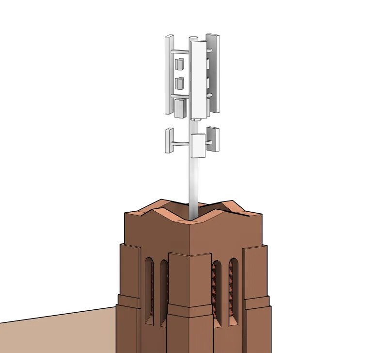
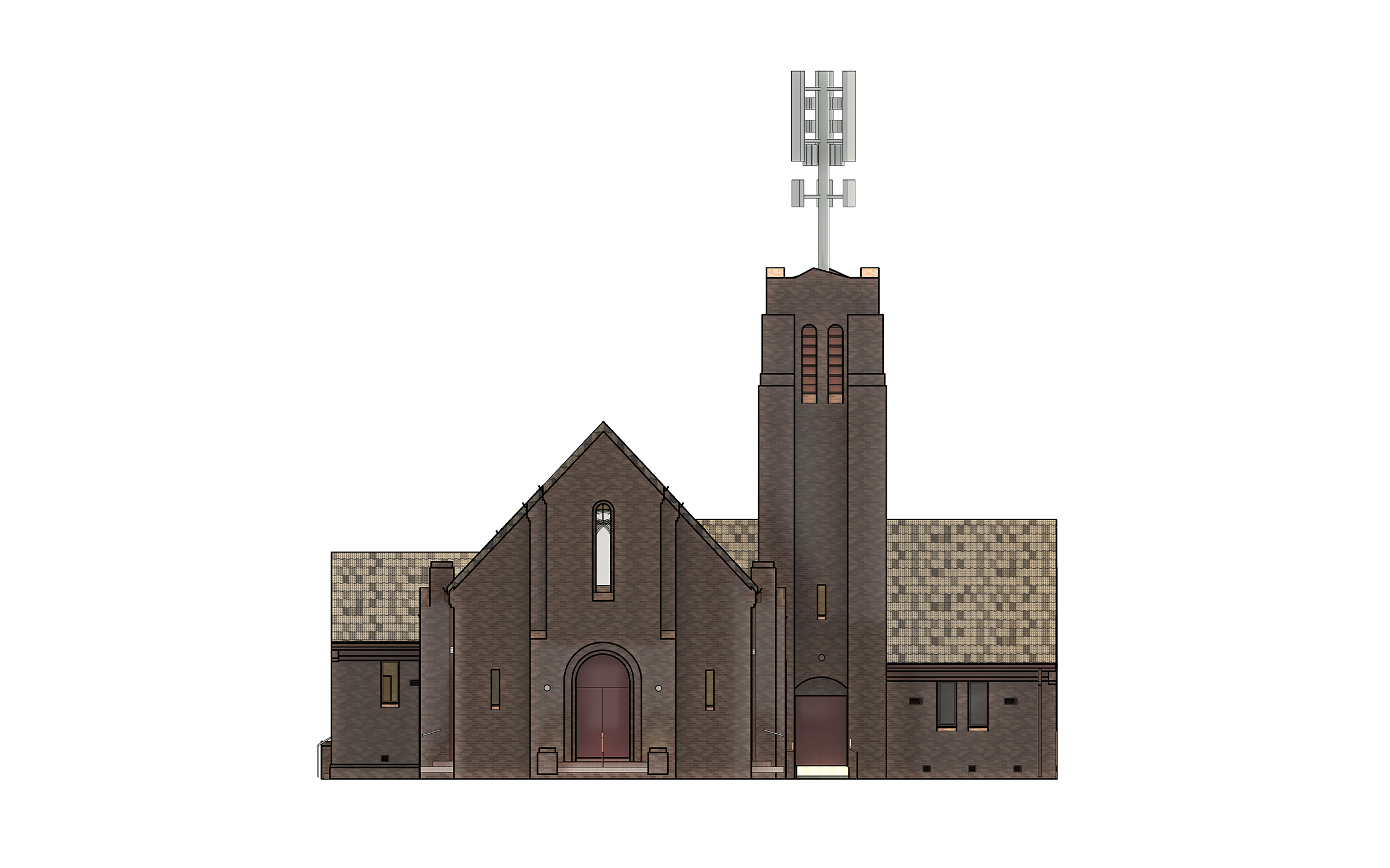
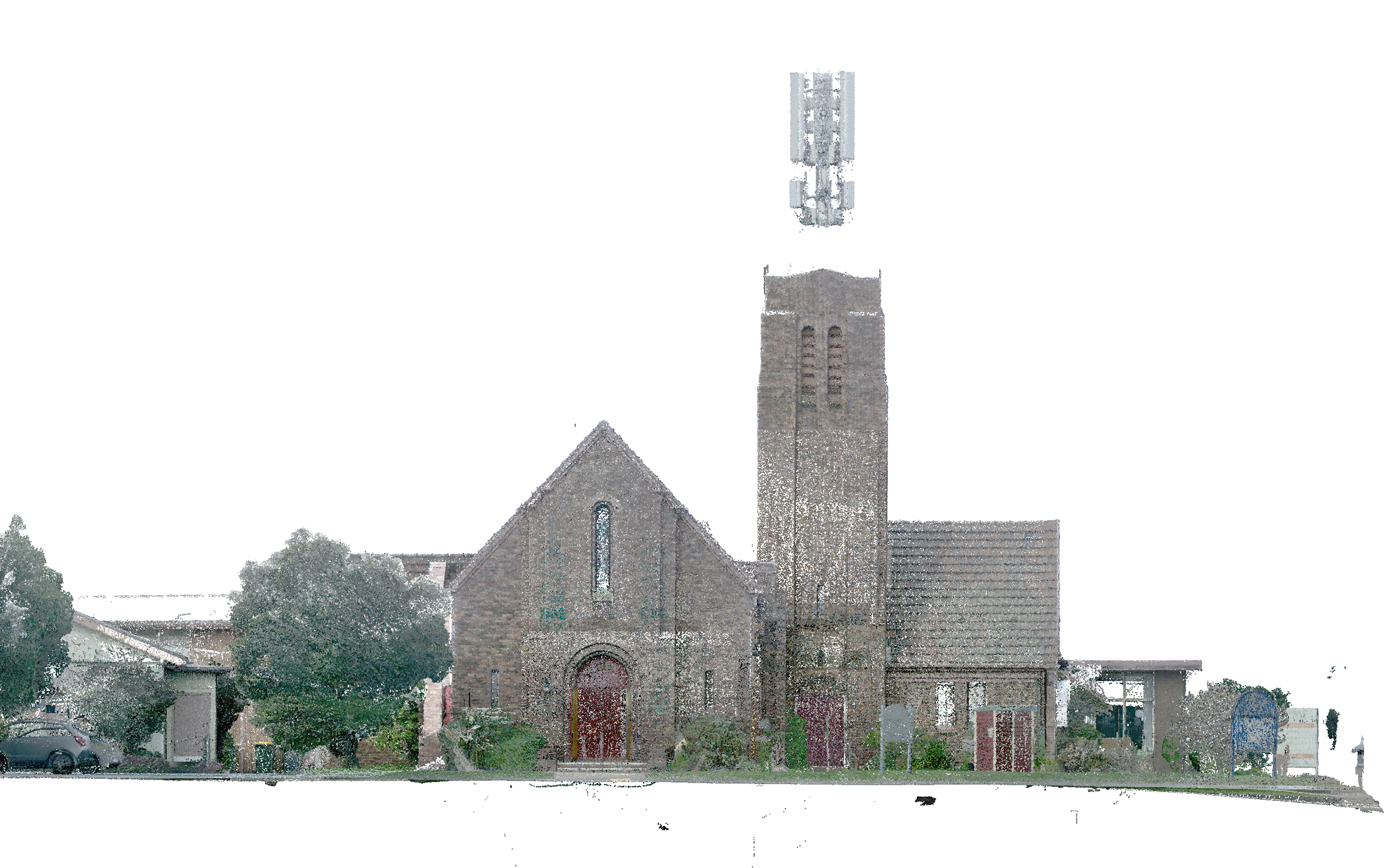
The central tower rises above the church roofline, with narrow vertical openings, recessed sections, and changes in profile along its height. The Revit model captures those transitions as well as the depth and placement of the openings, preserving the geometry of the existing tower.

Above the brickwork, the model shows the antenna as an assembly, including the central mast and its visible attachments. The scan data guided the sizing and placement of the individual components, documenting how they are arranged on the mast and how the assembly sits above the tower.

1
Point cloud vs model
1

Arched supports and roof framing

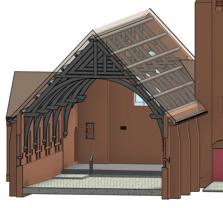
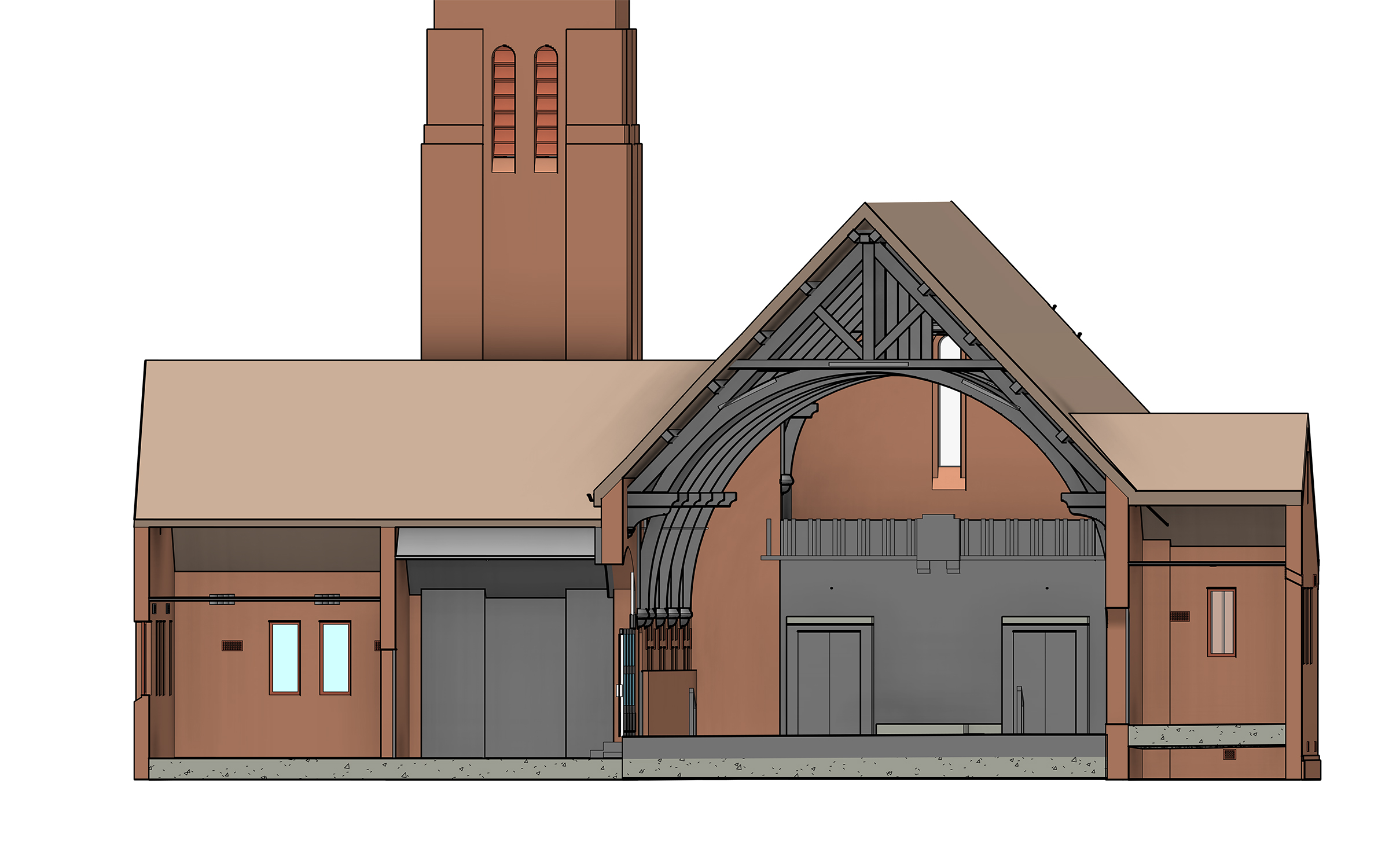
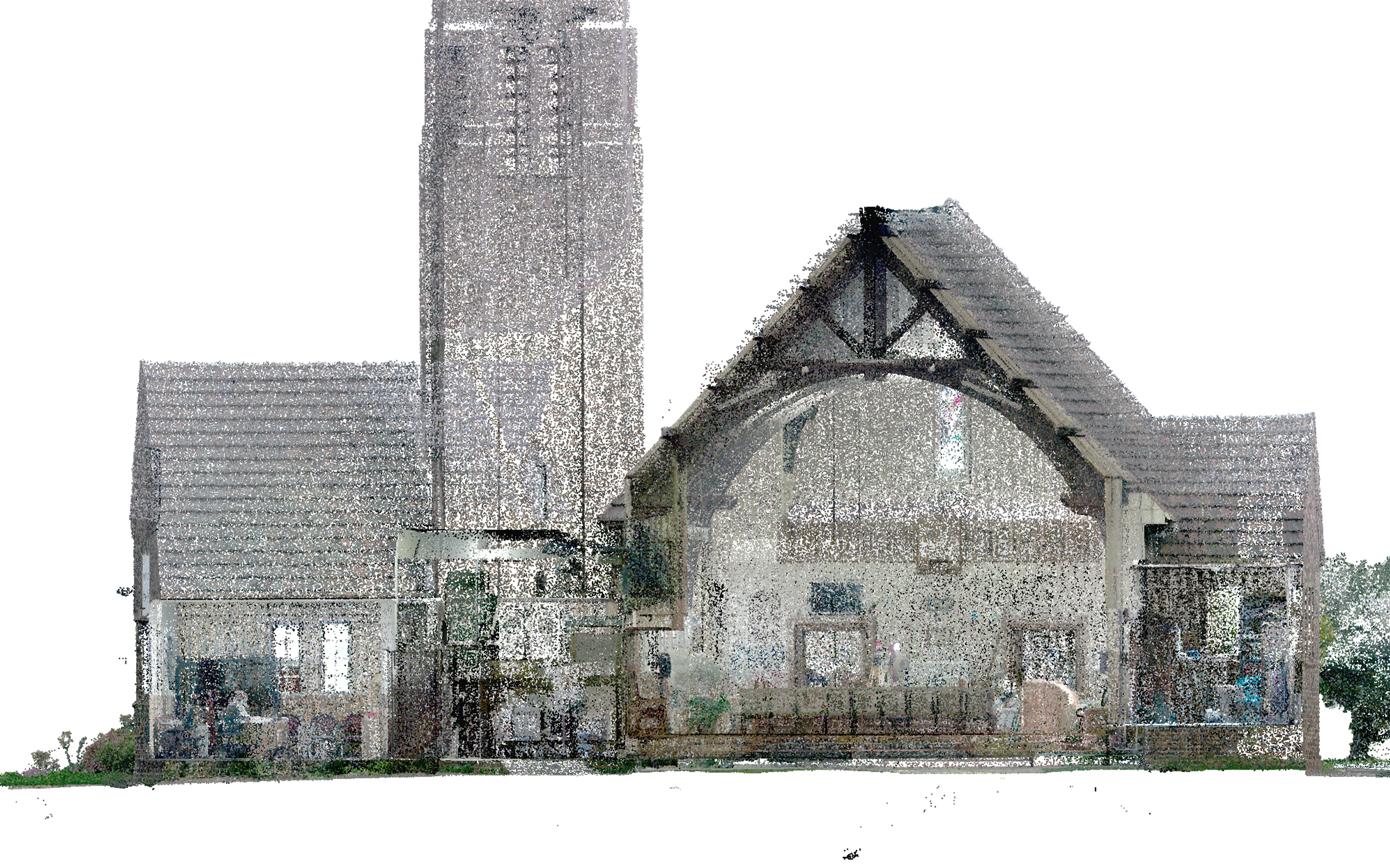
The church’s roof framing follows the irregular shape of the building. We used the point cloud to position the curved structural members, arched supports, rafters, and horizontal connecting members relative to the existing walls and roof slopes.

The junctions were as important as the individual members. We modeled where the curved supports meet the roof framing and how the main structural members transition into the adjoining roof sections. In section, the Revit model shows how the supports and framing fit together within the existing building.

Point cloud vs model

Exterior HVAC and building services

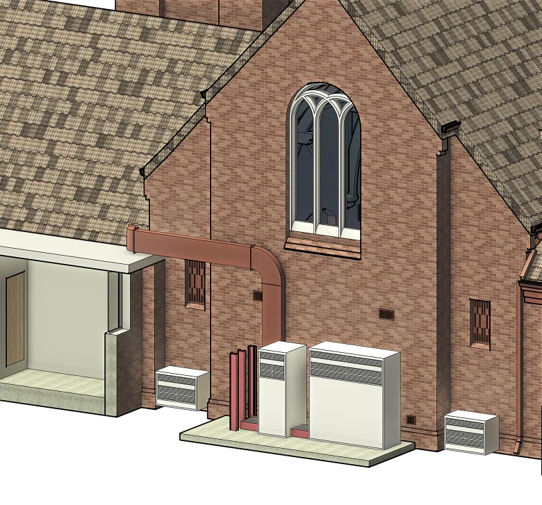
The exterior model includes the church’s visible building services, from outdoor HVAC units and ventilation components to associated piping and equipment platforms. Modeling the platforms alongside the units shows how the equipment is supported, as well as where it sits.

The Revit model records the size and position of the individual components and their arrangement along the facades. This gives the design team a reference for reviewing the existing services in relation to the surrounding architecture.

1
Point cloud vs model
1

The pipe organ and its supporting frame

Tall groups of pipes flank a lower central arrangement, giving the organ its distinctive profile. In Revit, we reproduced the dimensions and spacing of the visible pipes to capture the shape of each group and how the groups fit together.

The model also includes the framework around the organ. Modeling the frame and pipes together shows how the instrument sits within the church interior, in relation to the adjacent walls and arched roof supports.

Drawings

Click on preview to view high-resolution PDF drawings

Benefits
The LOD 300 Revit model and dimensioned as-built drawings give the design team a shared record of how the church, tower, and annex fit together before renovation or preservation work begins
The window tracery, decorative brick facade details, and pipe organ are documented in context, so the team can see which distinctive features a proposed change might affect
The model shows where the curved roof supports meet the rafters and horizontal connecting members, making it easier to review the existing framing before planning alterations
Outdoor HVAC units, ventilation components, piping, and support platforms are shown in relation to the facades, giving the team a reference for coordinating changes to exterior services
Tools used
1
Autodesk Revit
1
Autodesk ReCap
view project view more view photos