Search...
Overview

The main request of the client was to obtain a set of drawings, including:

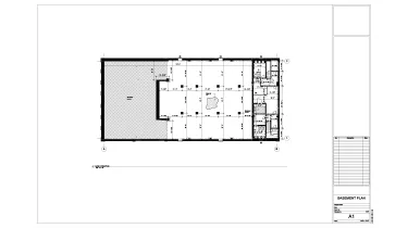
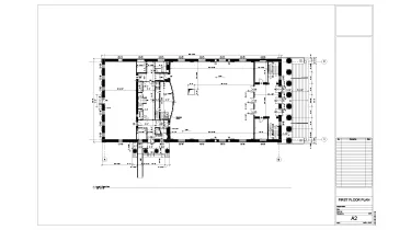
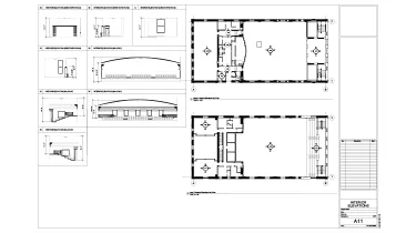
  • Floor plans for the basement, main level, and second floor;
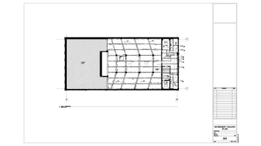
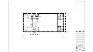
  • Reflected ceiling plans for the basement, main level, and second floor;
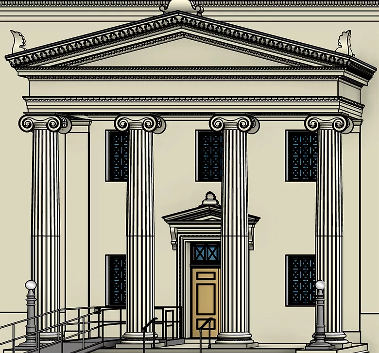
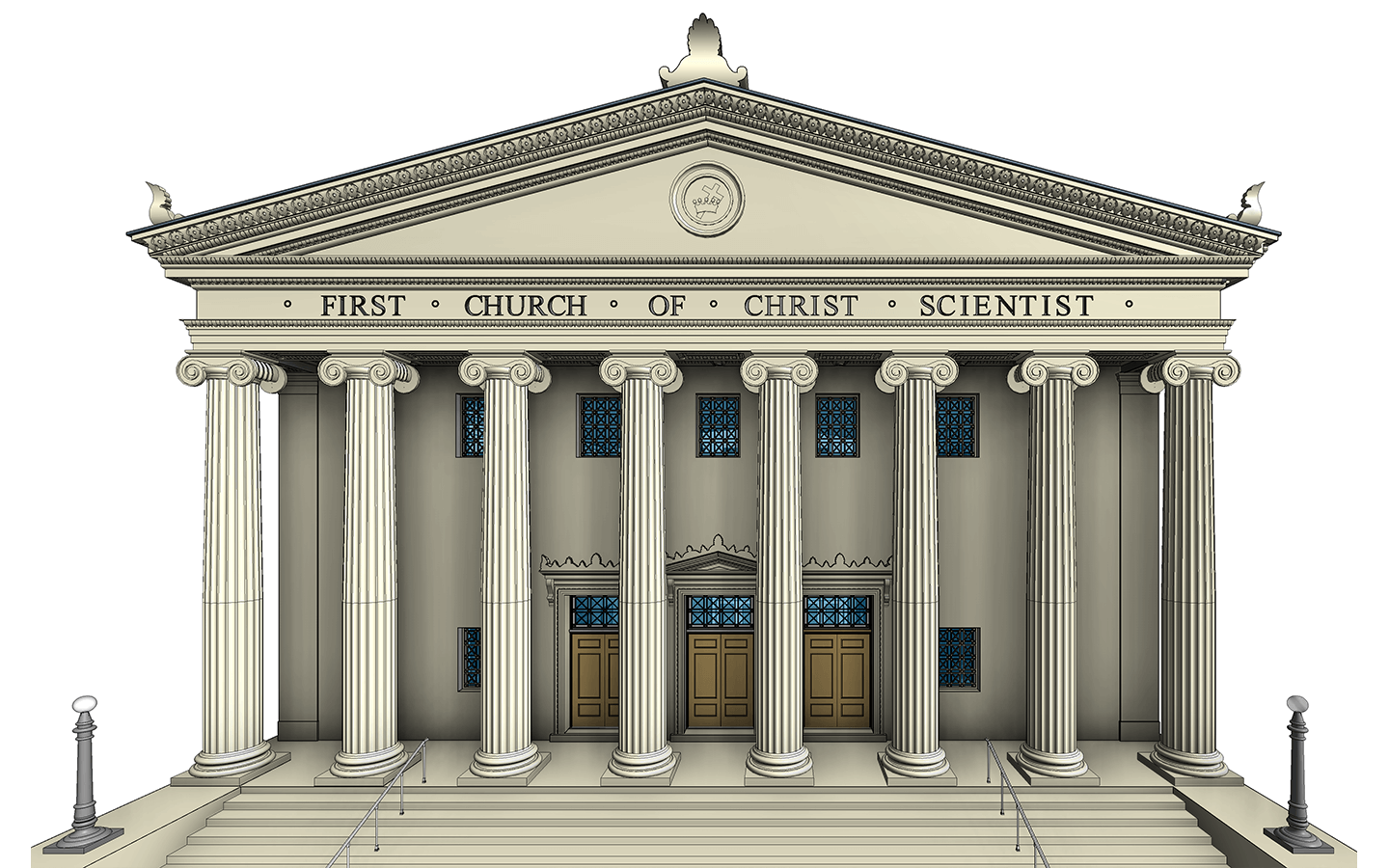
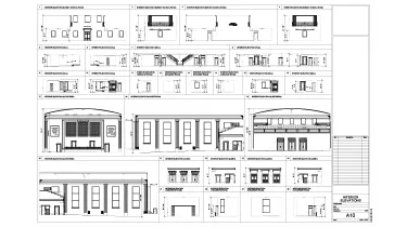
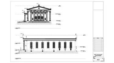
  • Exterior elevations for the north, south, east, and west;
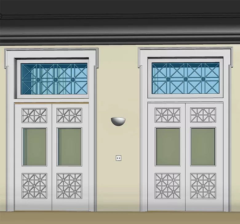
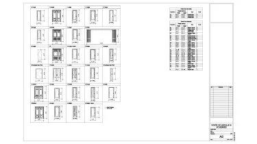
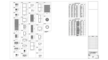
  • Window and Door schedules;
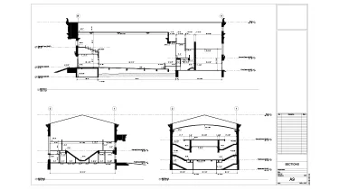
  • Interior section cuts, 3 in total;
  • Interior elevations, 34 in total.

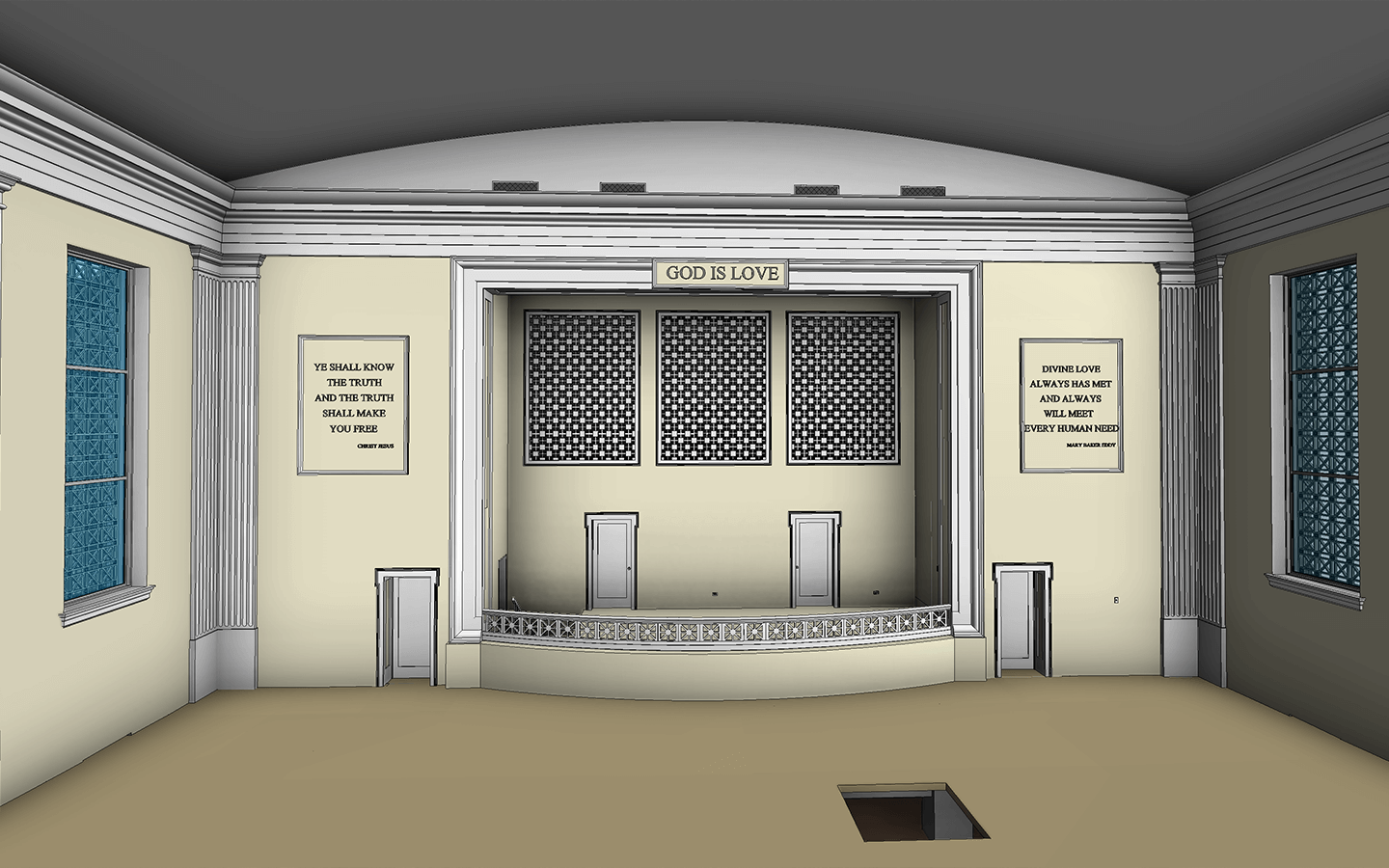
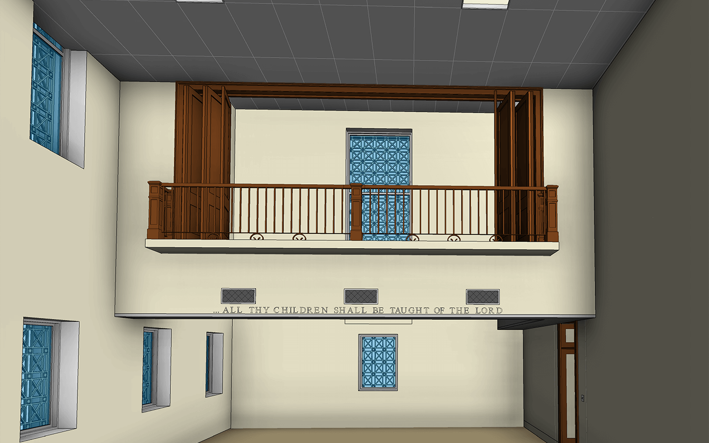
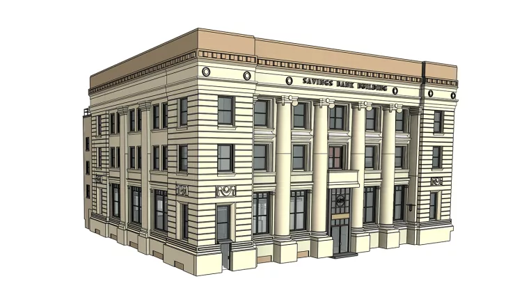
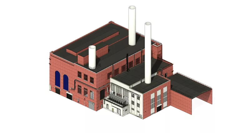
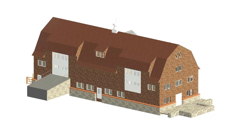
Taking into account the quantity of the drawings and the need for perfect coordination among them, it was decided to complete a full model of the Church. All the drawings were generated semi-automatically based on this model.

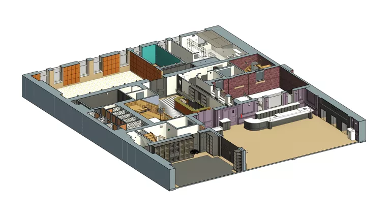
Scope of work: Create a highly detailed model of a 3-storey historical building featuring ornate exteriors, intricate interiors with complex railings, comprehensive MEP, and an extensive set of drawings (floor plans, RCPs, facades, interior elevations, window and door schedules).

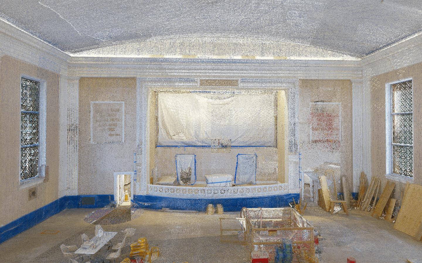
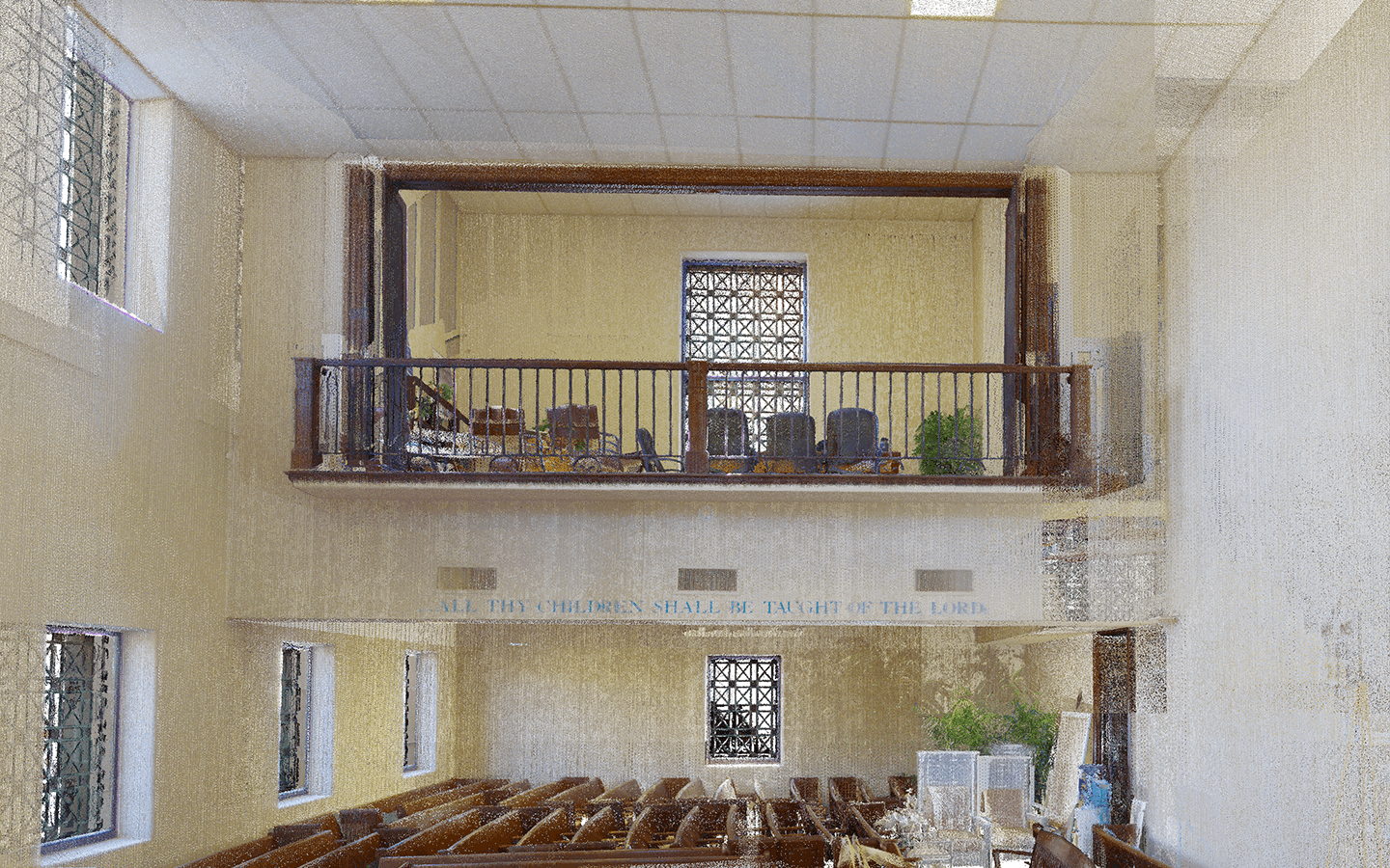
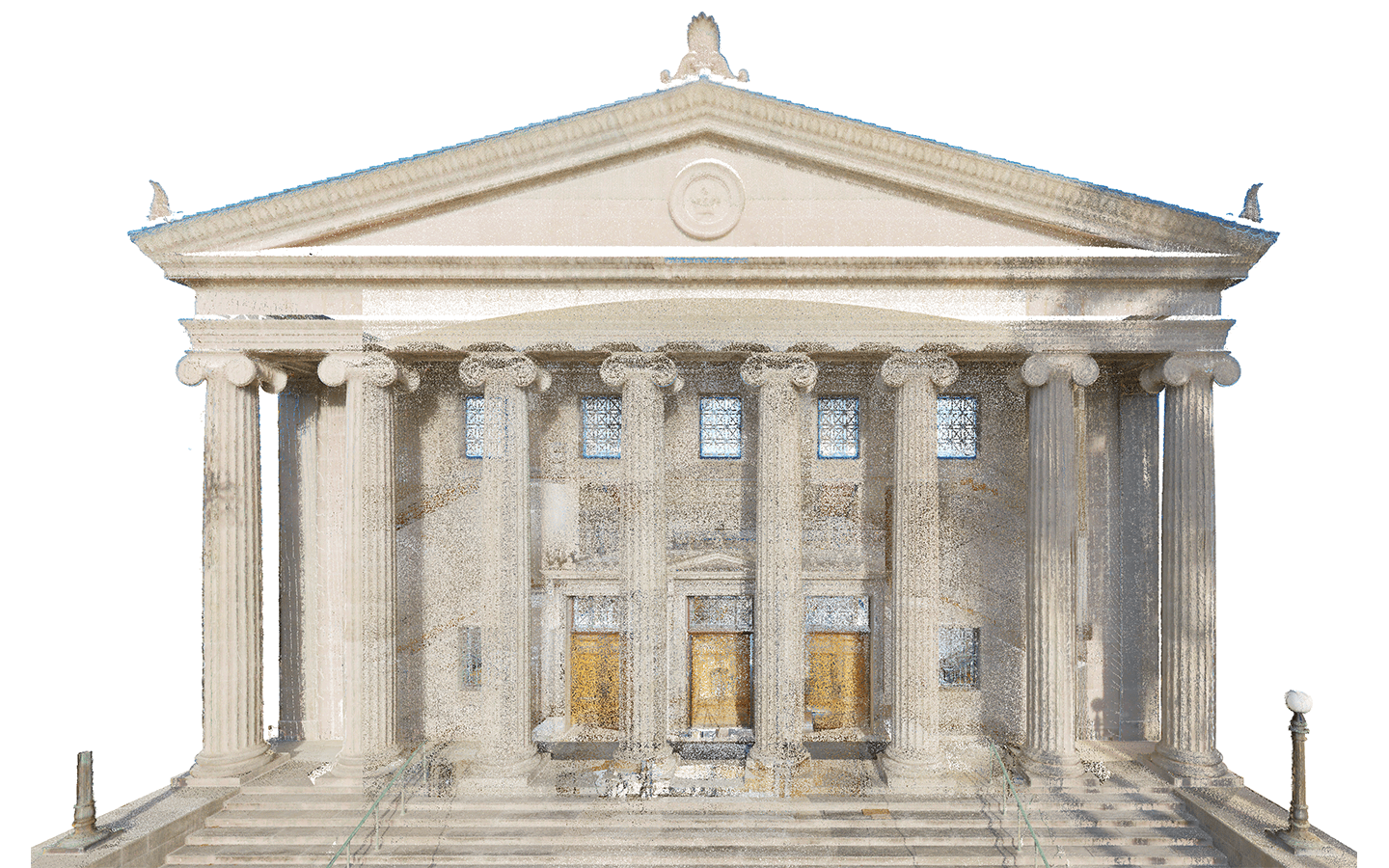
Input: Comprehensive Point Cloud of both interior and exterior. Photos of the interiors taken before the start of the reconstruction.

Output: 3D Model of interiors at LOD 350; A wide-ranging set of drawings.

Services: BIM, ARCHITECTURE, MEP
Subservices: Scan to BIM, As-built drawings
Industry: Institutional
Object type: Churches
Area: 3715 m² / 39990 ft²
Tools used: Autodesk Revit, Autodesk ReCap
Share:
Project stages
1. Receiving input
2. Analyzing the input: requesting any additional information and selecting the optimal team structure
3. Creating the basic architectural geometry: walls, floors, roofs, etc. which will serve as placeholders for subsequent details
4. Adding finer details to the model, inclusive of MEP
5. Generating drawings based on the completed model
6. Providing project support
1

Overall description

First Church of Christ, Scientist, located at 809 South Flagler Drive in West Palm Beach, Florida, is a historic structure that, on December 3, 1998, was determined to be eligible for listing on the National Register of Historic Places. However, the owner objected to the property being listed on the Register. It is still a functioning Christian Science church.

Point cloud vs Model
Interior detailing

Some rooms required the creation of interior elevations for the entire perimeter, while others did not require the creation of drawings. The emphasis on detail was placed on the rooms that required the elevations. After evaluating the appropriateness of creating volumetric baseboards, moldings, and wall texts, we concluded that it would be more optimal to add these elements as lines visible in 3D views (using the Split Face tool). This approach accelerated the detailing of the room, removed the necessity to hide 3D baseboards on plan views to avoid overloading them, and simultaneously ensured the interior elevations were detailed enough.

Additionally, some areas were already under reconstruction when laser scanning occurred. These areas were mainly covered temporarily with film, so some of the areas were recreated in Revit, using older photos as references to define the hidden elements’ appearance.

Point cloud vs Model

Exterior embellishments

The exterior of the church is adorned with various embellishments and classical elements such as:

  • Ionic columns
  • Coffered ceilings combined
  • Acroterions
  • Entablature
  • Cornices with repetitive 3D patterns
  • Pediments
  • Decorated window grills, etc.

The main principle we adhered to during modeling was avoiding model-in-place elements. All the applied decorative elements are loadable families. For example, cornices with repetitive 3D patterns were made with a generic model line-based category.

1
Point cloud vs Model
1

Door and window schedules

Despite having only graphical information on the overall drawings, it was requested to have door and window schedules that showed opening sizes, the number of instances used in the building, and descriptions of their types. With these requirements in mind, all door and window elements were modeled considering the future operations that would be done with them:

  • Exterior grills were modeled as separate elements so as not to interfere with window legends;
  • Blocks, where doors have windows above, were modeled as separate elements with different categories to enable automatic placement in different schedules.
Benefits
Quick generation of a bunch of drawings based on the 3D geometry created
100% coordinated drawings with no discrepancies between them
Automatic and adaptive window and door schedules
Tools used
1
Autodesk Revit
1
Autodesk ReCap
view project view more view photos