Search...
Overview

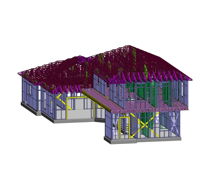
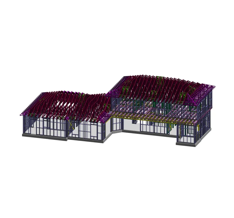
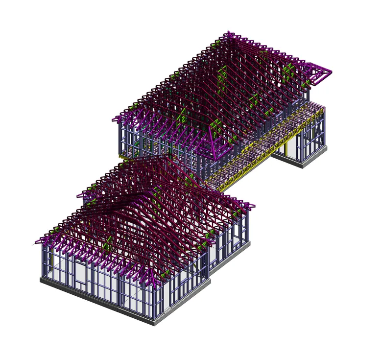
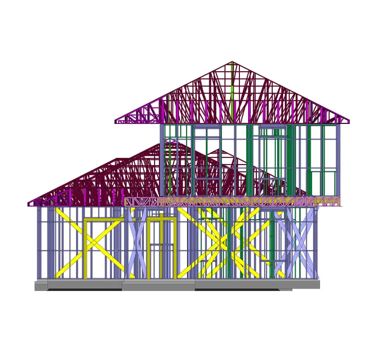
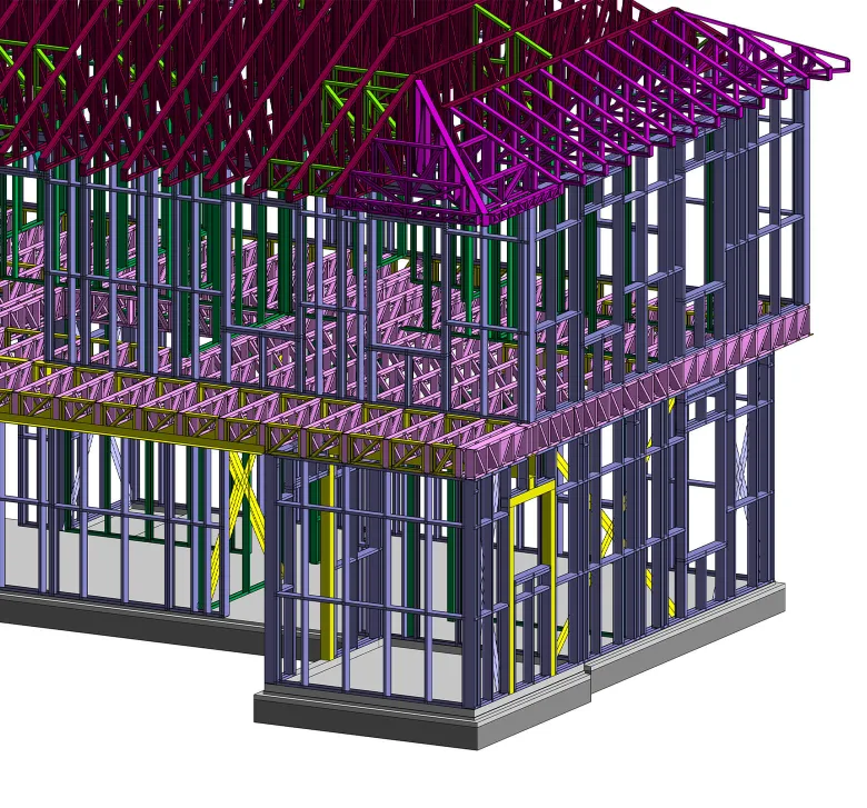
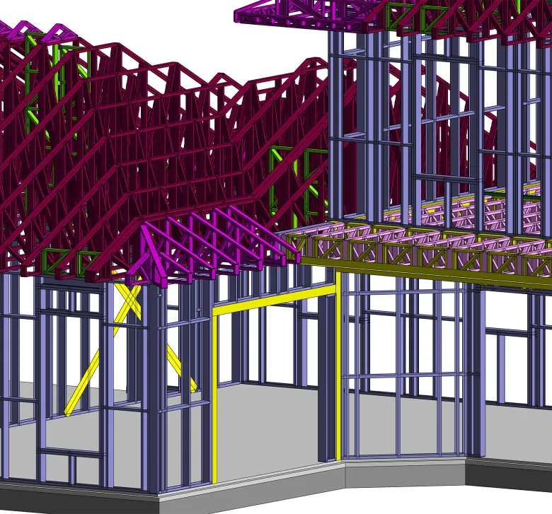
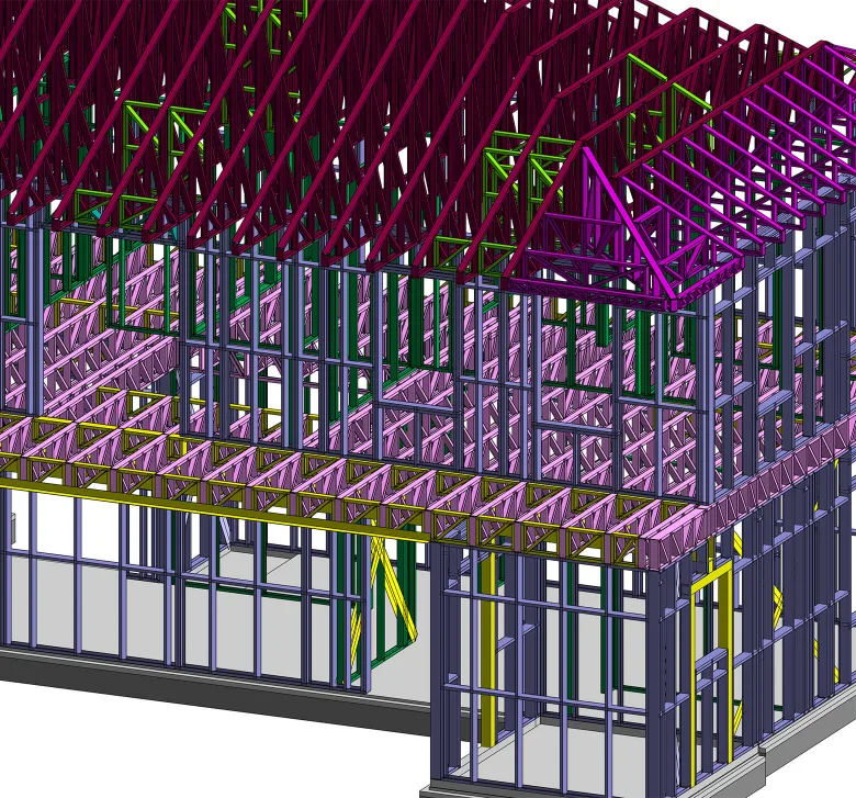
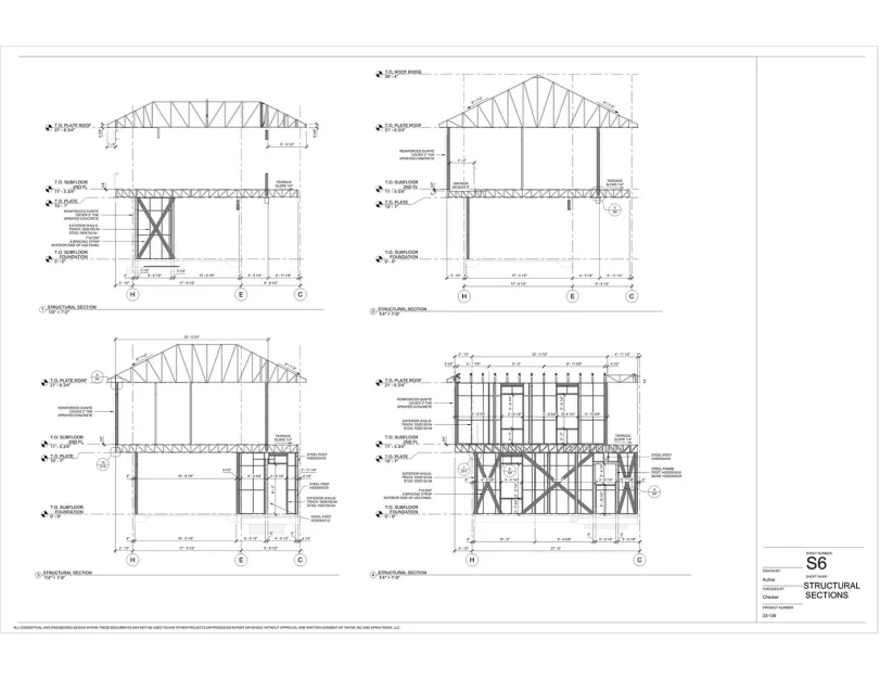
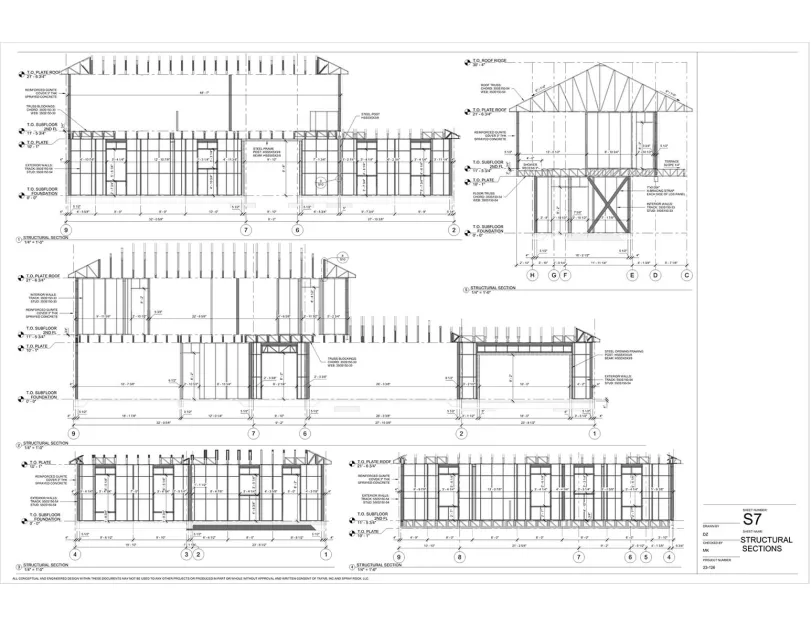
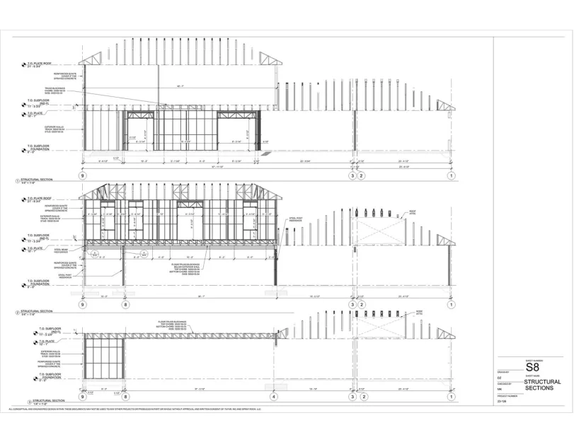
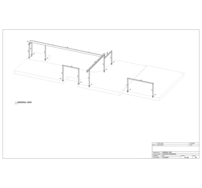
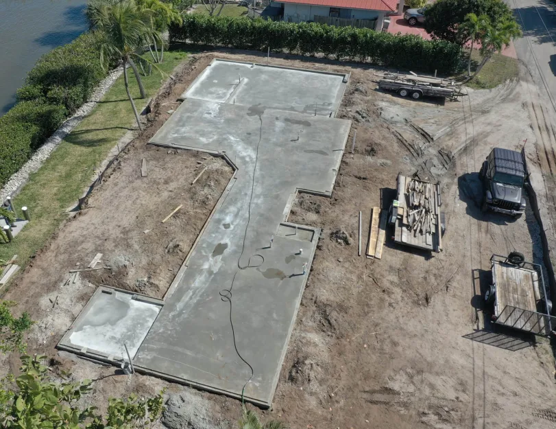
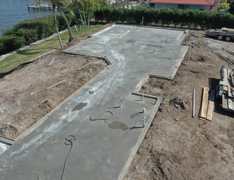
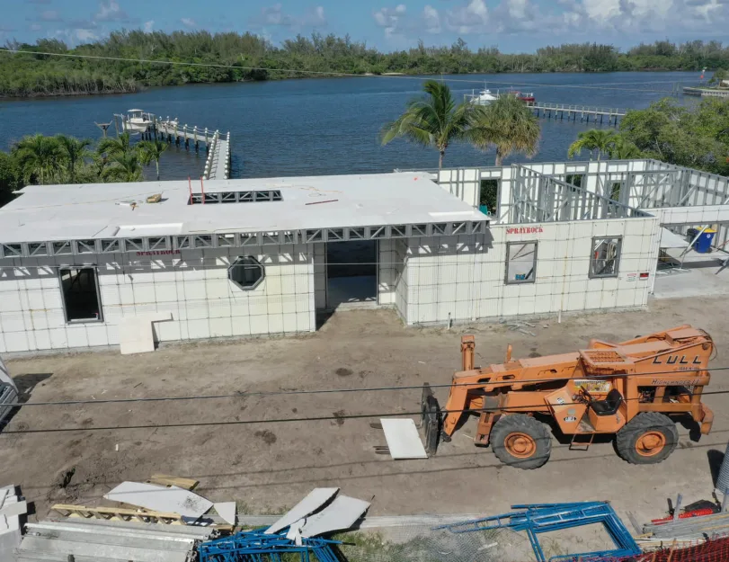
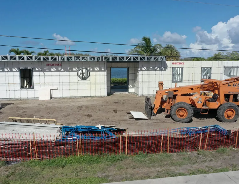
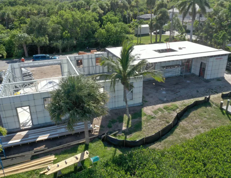
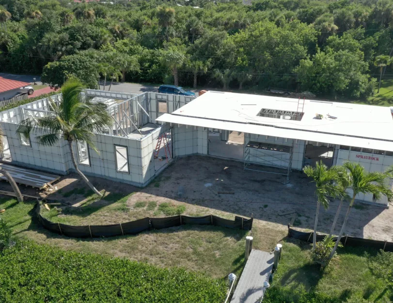
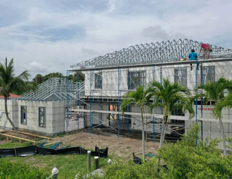
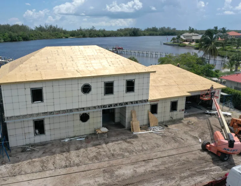
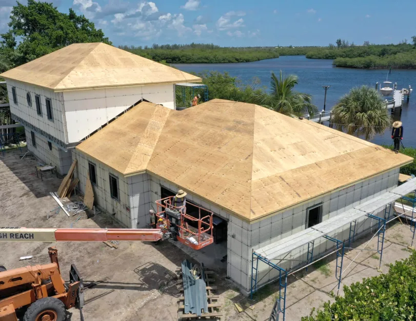
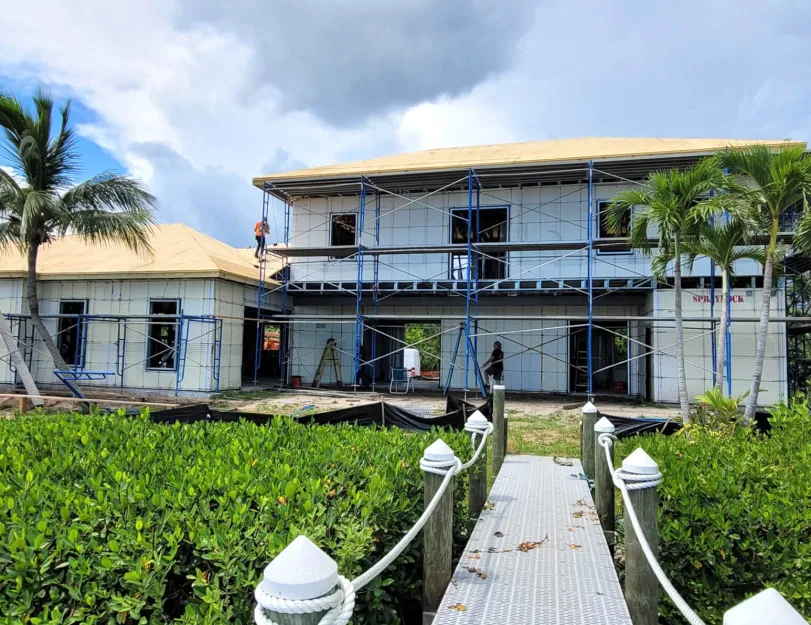
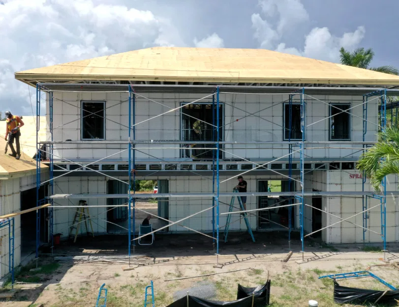
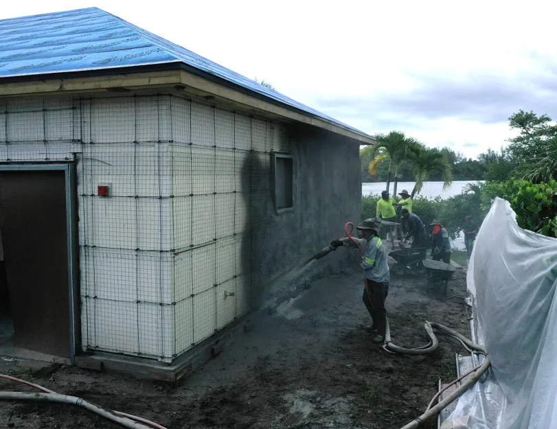
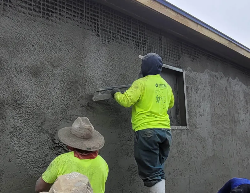
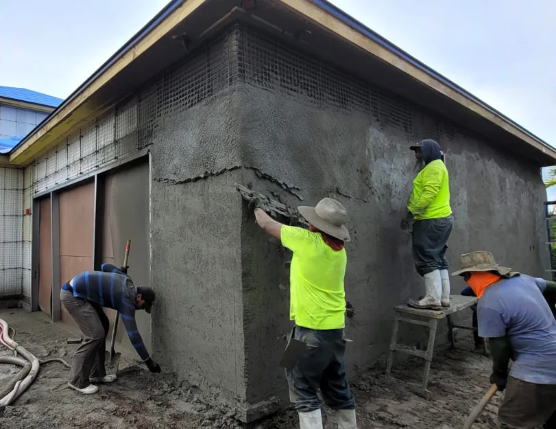
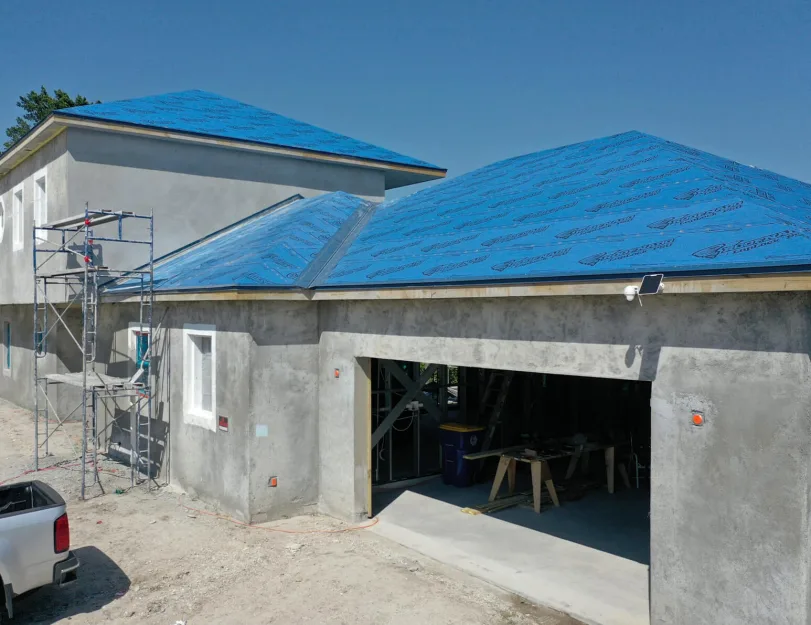
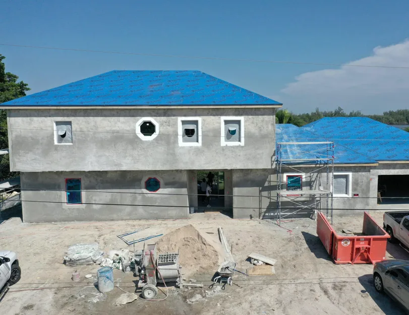
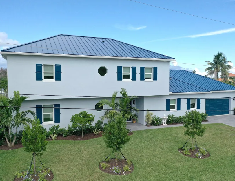
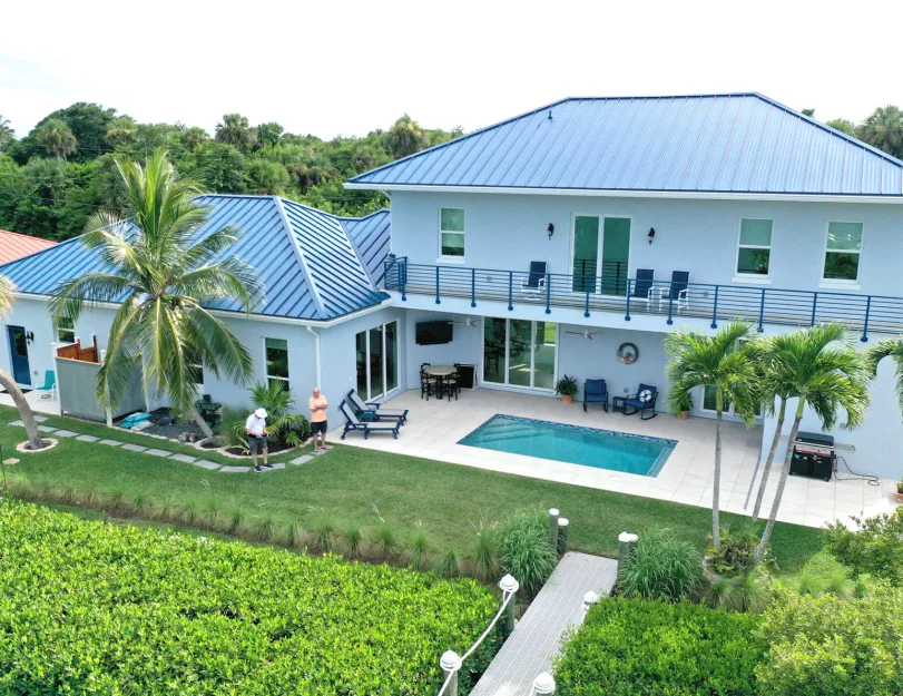
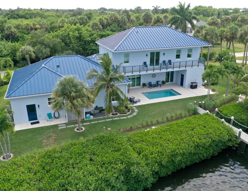
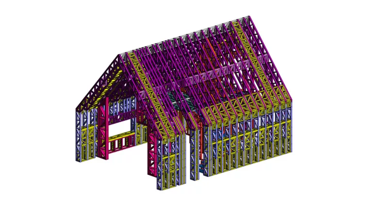
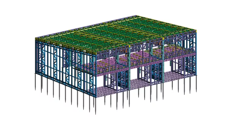
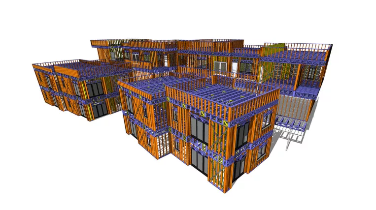
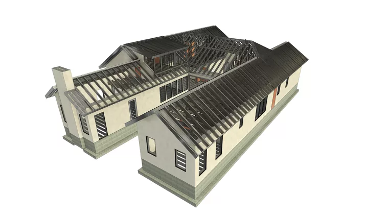
A seemingly typical two-story residential house, this project came with a big twist because of its unconventional construction approach.

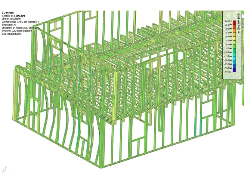
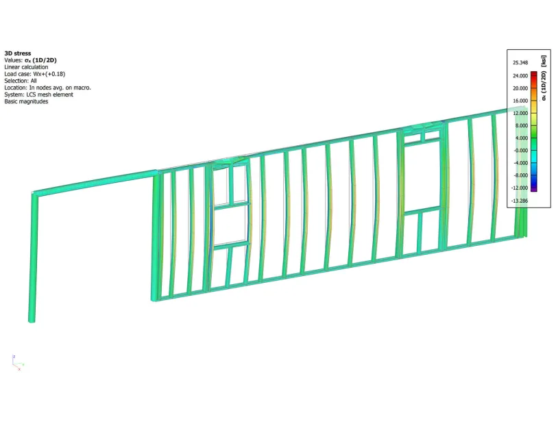
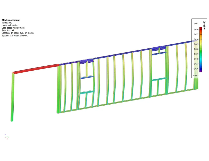
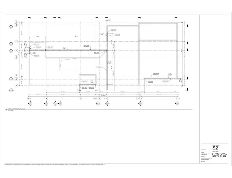
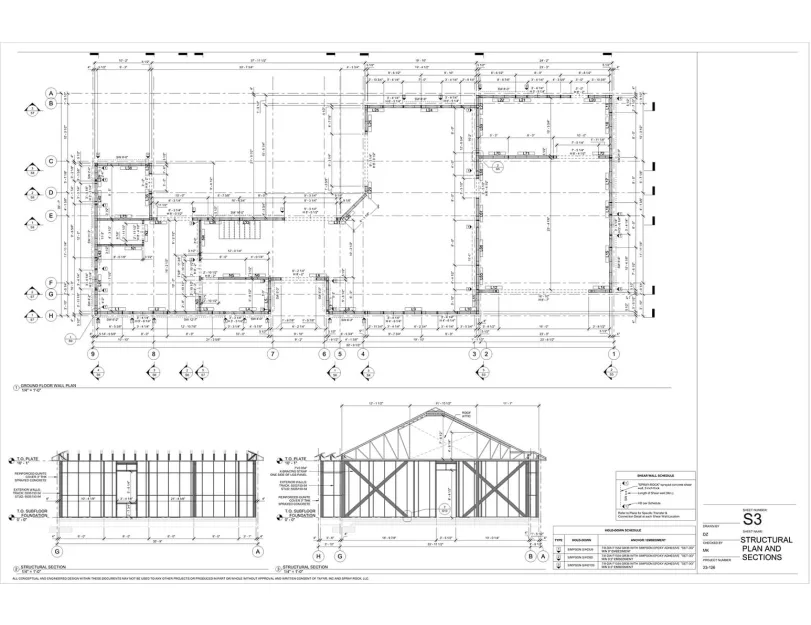
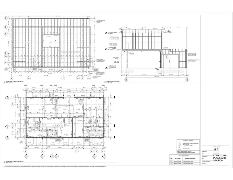
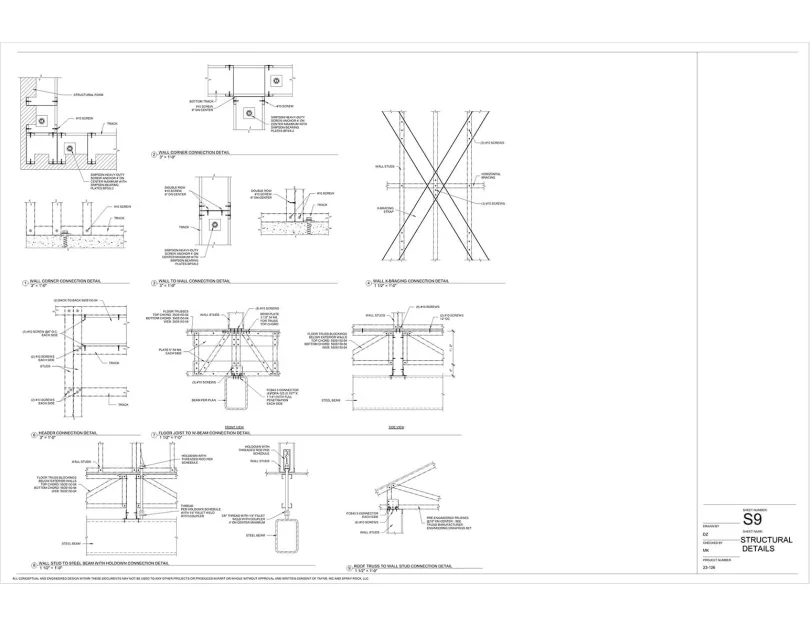
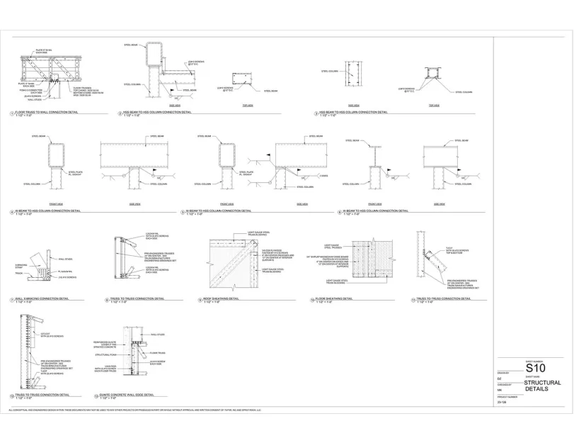
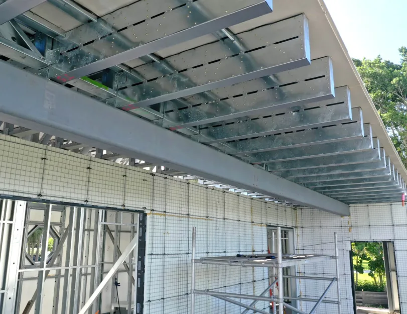
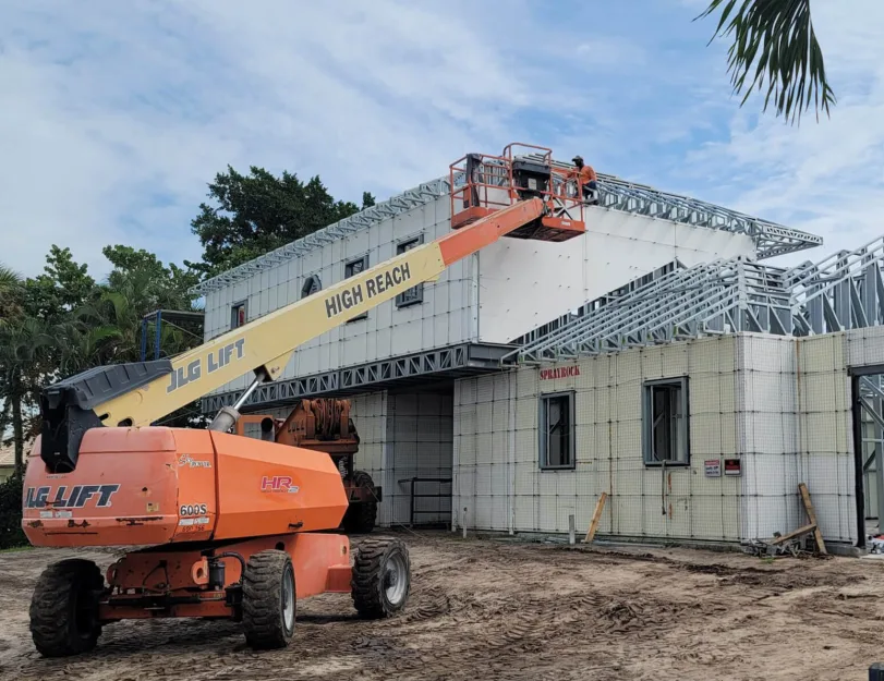
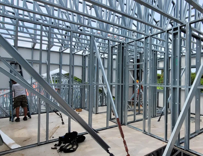
The project’s uniqueness lay in the fact that the construction company used a patented technology of spraying gunite mixture onto the rebar attached to prefabricated LGS panels. Therefore, from the foundation to the roof eave, this project was completely different from any other US standard LGS building.

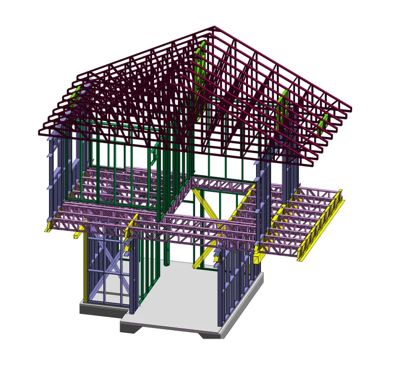
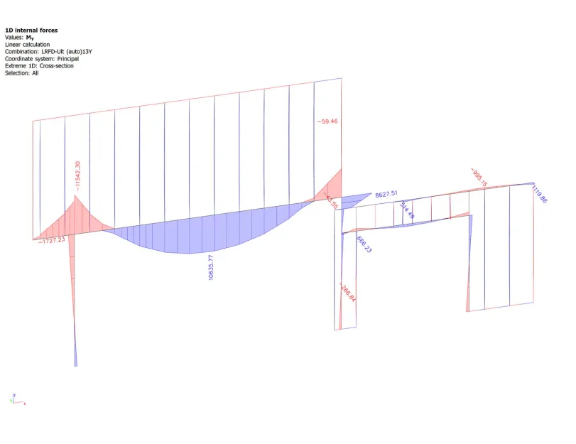
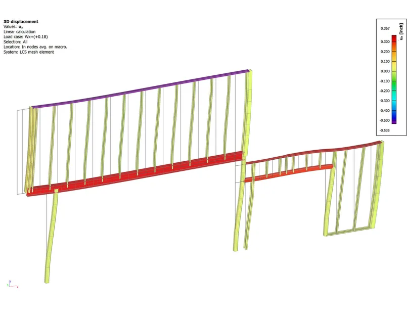
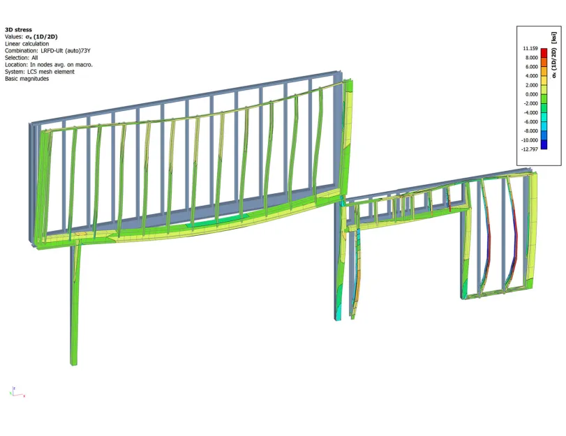
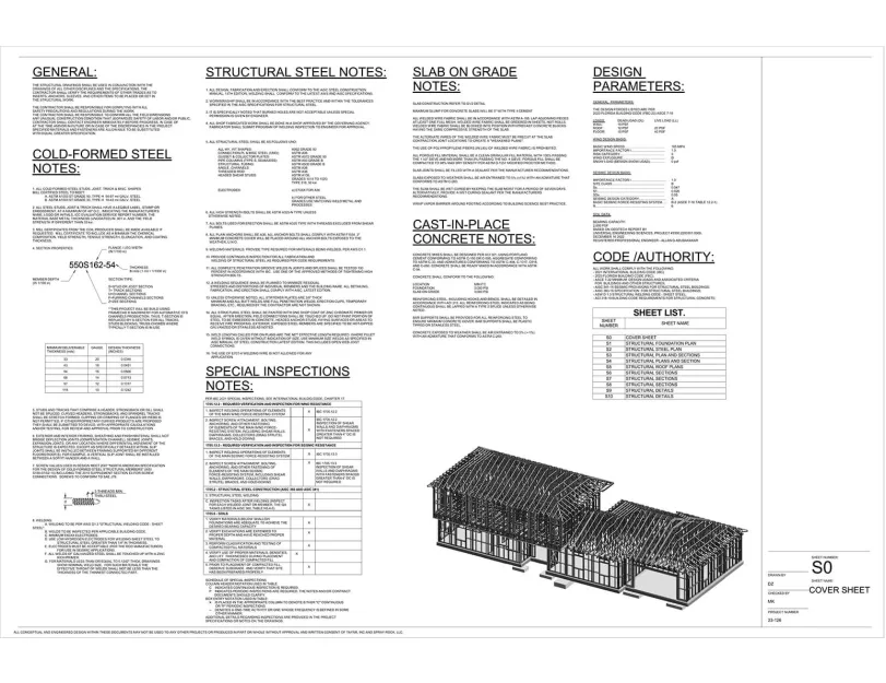
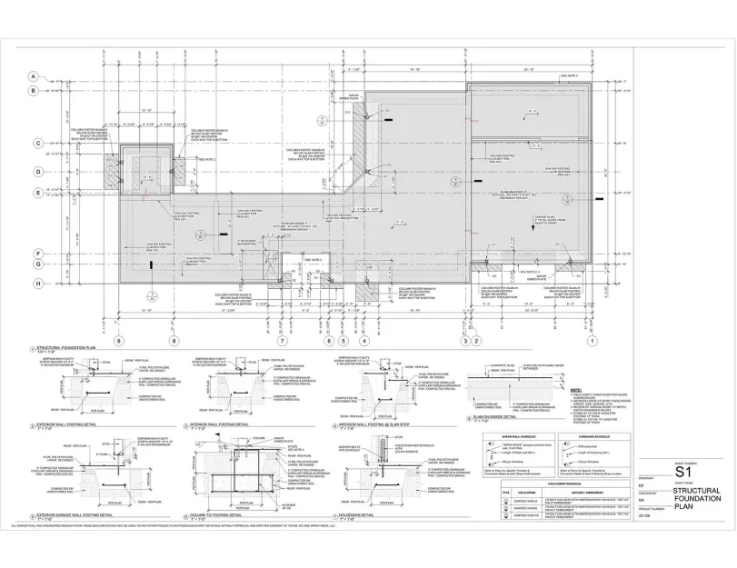
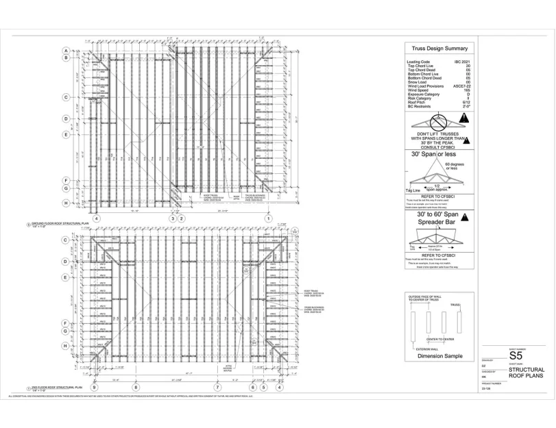
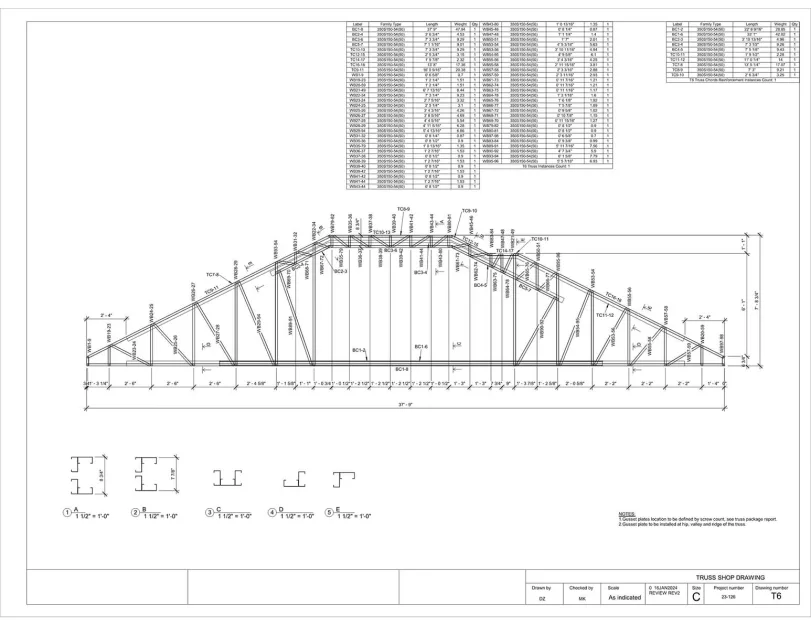
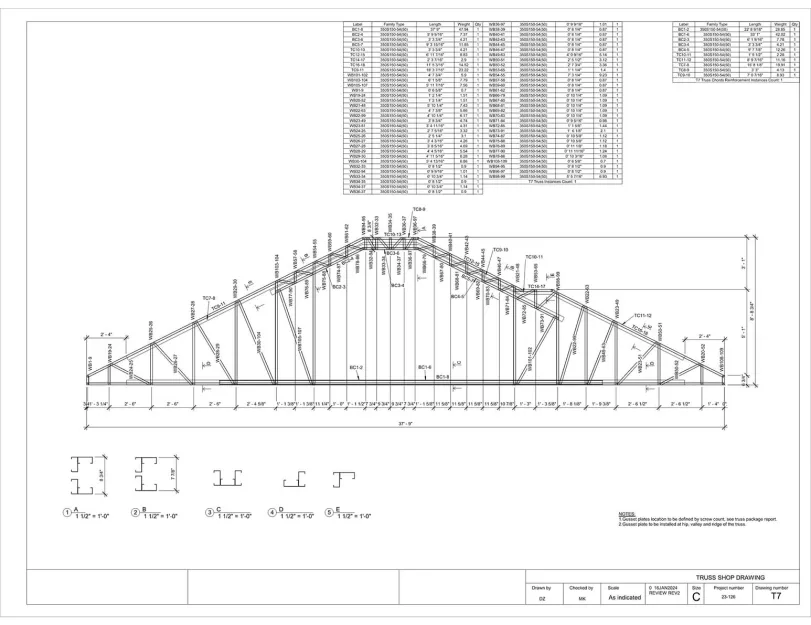
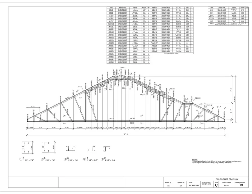
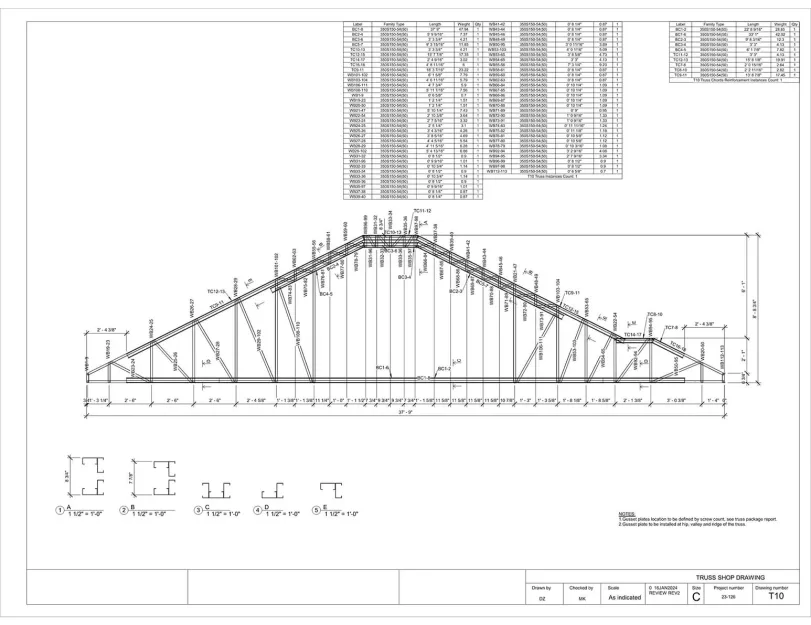
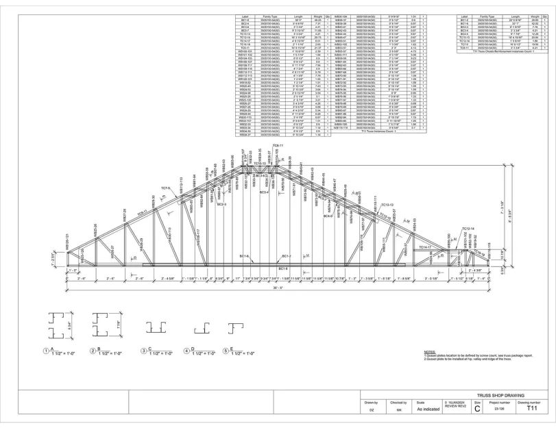
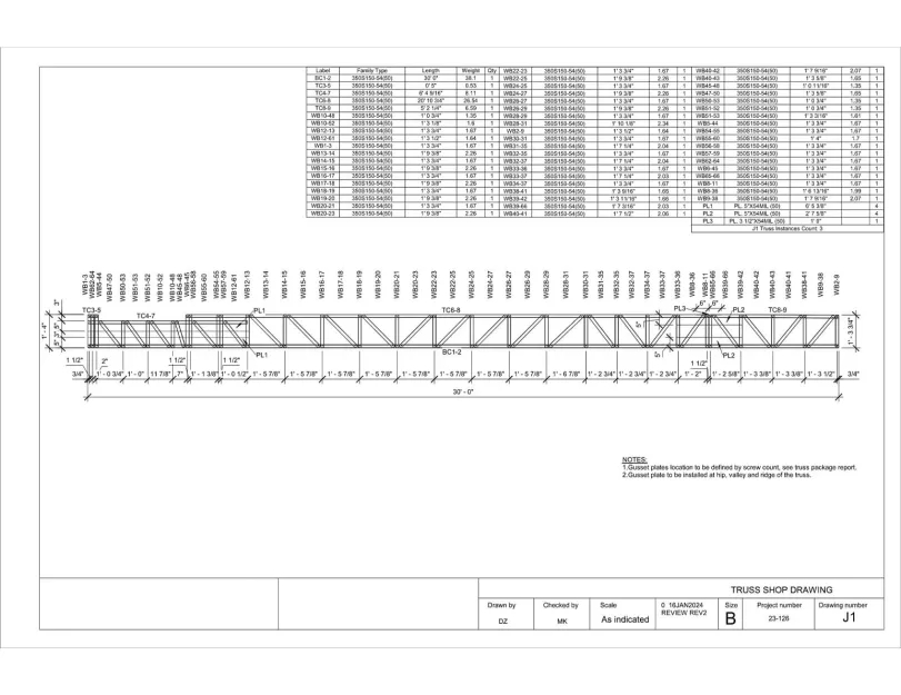
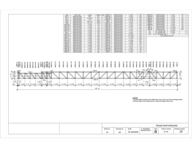
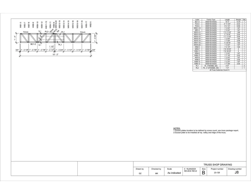
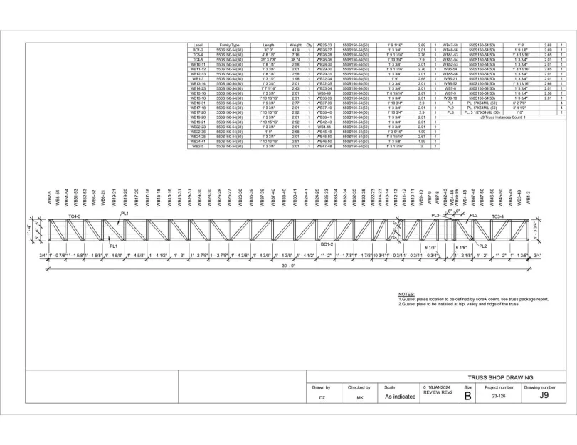
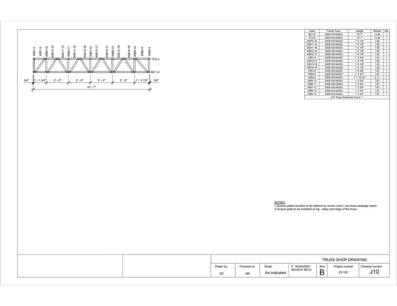
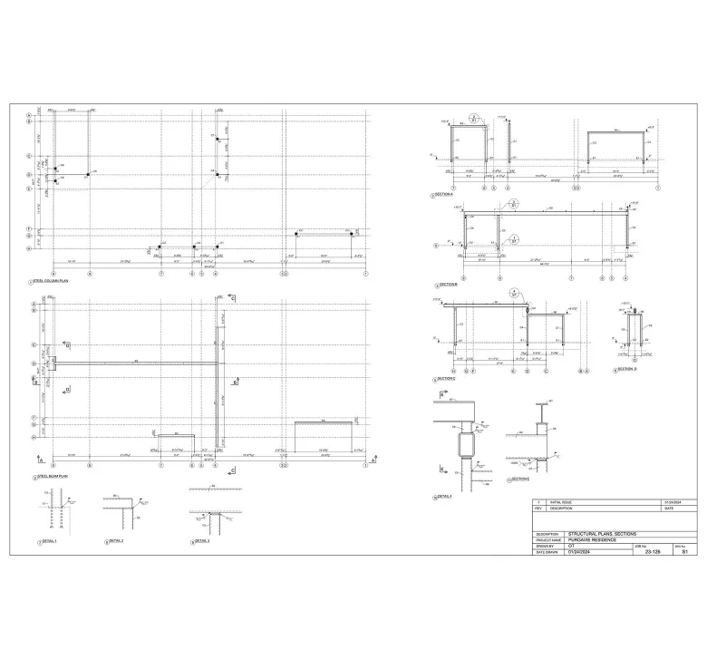
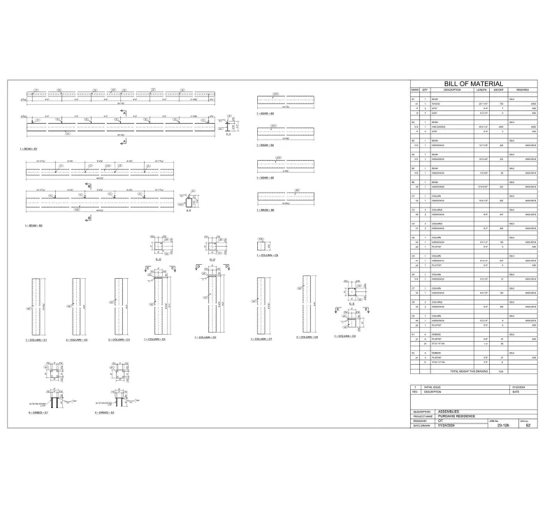
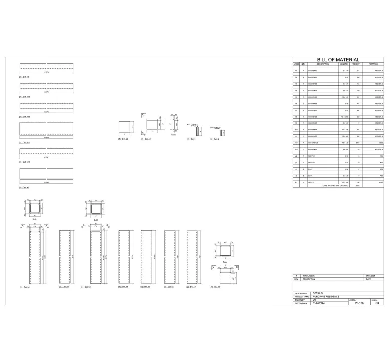
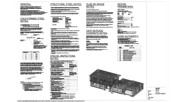
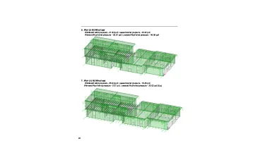
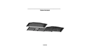
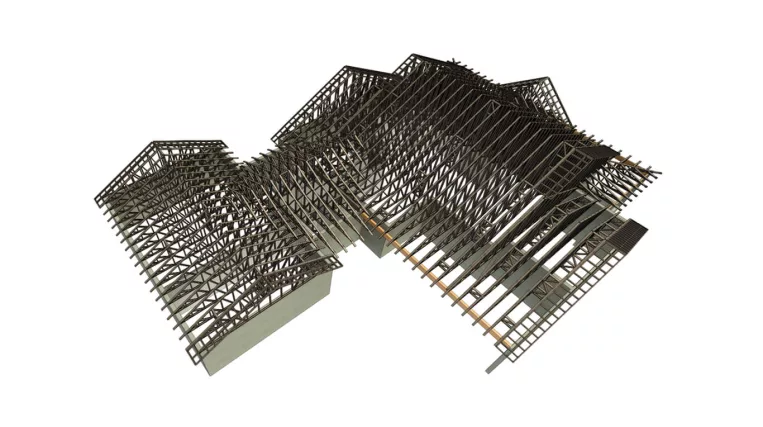
To cover every step from concept to fabrication, the ORIGIN team was requested to create a range of deliverables: structural construction drawings, the structural analysis for the LGS framing and foundation system, and CNC files for the Framecad machine. Not to mention, strict compliance with multiple codes and standards was non-negotiable, too.

Input: Architectural drawings set

Project deliverables:

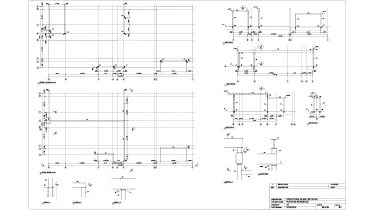
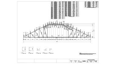
  • Structural drawings set;
  • Structural analysis report;
  • LGS shop drawings;
  • Framecad CNC files for LGS panels production.
Category: STRUCTURE
Services:LGSF design and detailing, Hot-rolled steel design and detailing, Construction drawings, Prefabricated construction services, Hot-rolled steel framing, Cold-formed steel framing
Industry:Residential
Object type:Single-family home
Area:304 m² / 3275 ft²
Tools used:Autodesk Revit, Strucsoft MWF Advanced Metal, SCIA Engineer, Tekla Tedds
Share:
Project stages
1. Revit model creation
2. Structural analysis and report
3. LGS and hot-rolled steel framing creation
4. Structural drawings production
5. LGS CNC export and shop drawings
Code/Authority List:
  • 2019 Florida Building Code (FBC);
  • 2019 Edition of the International Building Code;
  • ASCE 7-16 Minimum Design Loads and Associated Criteria for Buildings and Other Structures;
  • Steel design: AISC 360-10/05: ASD;
  • Cold-Formed steel: AISI S100-16w;
  • Seismic AISC 341-10/05;
  • Concrete: Reinforced Concrete Design Handbook (ACI);
  • Ultimate Strength Design Handbook (ACI).
1
1
1
1
1
1
1
1

Revit modeling

Starting off, our team had to thoroughly study technical documents before proceeding with the project.

First, we studied architectural drawings and built a conceptual structural scheme. At this phase, it was important to verify whether the architectural layouts would work structurally. All issues were noted and addressed to the lead architect for adjustments.

Then, we turned the PDF architectural drawing set into a clean Revit model. It consisted of the foundation, floors, roofs, and walls, which served as the host for the future LGS framing.

Structural analysis and report

Once preliminary Revit modeling was completed, we started to run structural analysis of the whole structure. Parallel with the preparation of the Revit model geometry, a structural analysis was carried out to gather all acting loads, define load paths, perform overall and local calculations, and design critical bearing elements and connections, including value engineering on specific demanding cases.

LGS framing calculations were performed using Scia Engineer, while masonry walls and foundation calculations were carried out with Excel and Mathcad spreadsheets. This way, we could achieve a high level of accuracy, flexibility for custom calculation methods, quick iterative changes, and transparent documentation.

1
LGS and hot-rolled steel framing creation

With the structural calculations complete, we began modeling the LGS framing in the Revit host model. To streamline the process, we used Strucsoft MWF Advanced Metal—a Revit add-in with tools for automated LGS framing. Throughout, we accounted for floor, roof, and wall thicknesses, openings, and other constraints. Where LGS members were insufficient, we designed hot-rolled steel elements.

Connections design and calculations
Framing design and calculations
Structural drawings production

Our next step was preparing Revit views: plans, sections, elevations, details, and other necessary drawings.

With the completed structural model, no manual drafting was required, making drawing production the easiest part — the only task left was adding dimensions, annotations, and notes. Once completed, we sent the plans to the building department for approval.

Structural drawings
LGS CNC export and shop drawings

Once the plans were approved, the ORIGIN team moved on to the final step — LGS panel production.

This process consisted of two steps: producing members of LGS panels and assembling LGS panels from the members.

First, we exported a CNC file from the Revit model and loaded it into the Framecad rollformer. As the machine produced the profiles, the assembly phase began. For this, we provided shop drawings for each panel, with every member clearly labeled and dimensioned.

Shop drawings
1
1
1
1

Tackling the complexity of LGS truss shop drawings

Some areas of this building had large spans, complex structural solutions raised by architectural and HVAC requirements: limited heights, large spans, and unspecified openings inside the structural members. Thus, LGS trusses could not handle applied forces without reinforced chords and gusset plates.

For such trusses, we decided to develop shop drawings using Tekla Structures. This approach sped up the drawing production process and also provided detailed steel specifications for all gusset plates.

For Hot-rolled steel members, we used Tekla Structures, which helped to perform specifications for both individual parts and small details like individual bolts.

Construction site
Benefits
Eliminated installation issues on site, thanks to the precise match of LGS framing with the building geometry
Streamlined clash detection with other trades through the BIM model of LGS and Hot-rolled framing
Significantly reduced manufacturing time by using CNC exports for LGS panels and Hot-rolled steel members production
Tools used
1
Autodesk Revit
1
Strucsoft MWF Advanced Metal
1
SCIA Engineer
1
Tekla Tedds
view project view more view photos