Search...
Overview

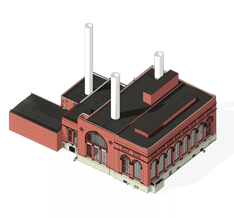
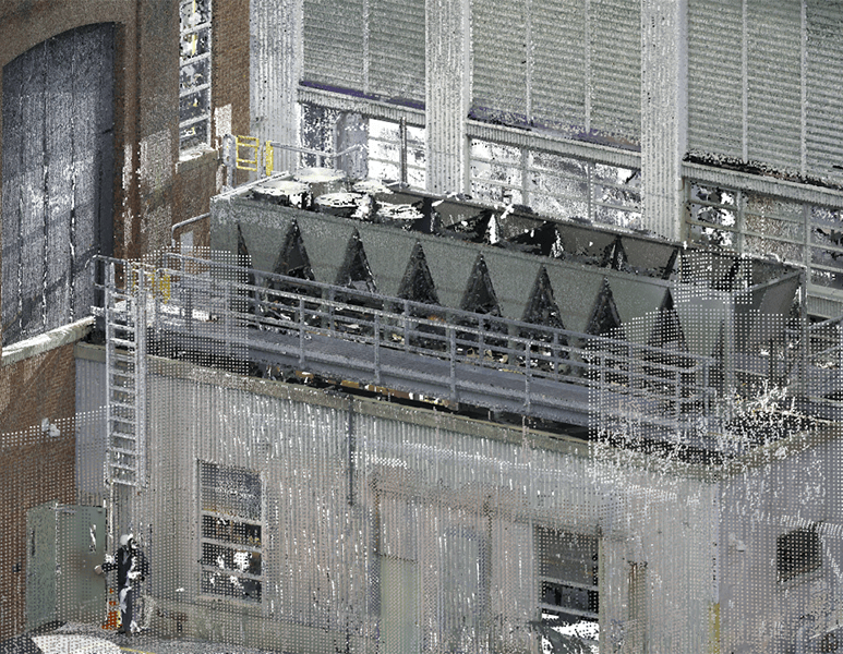
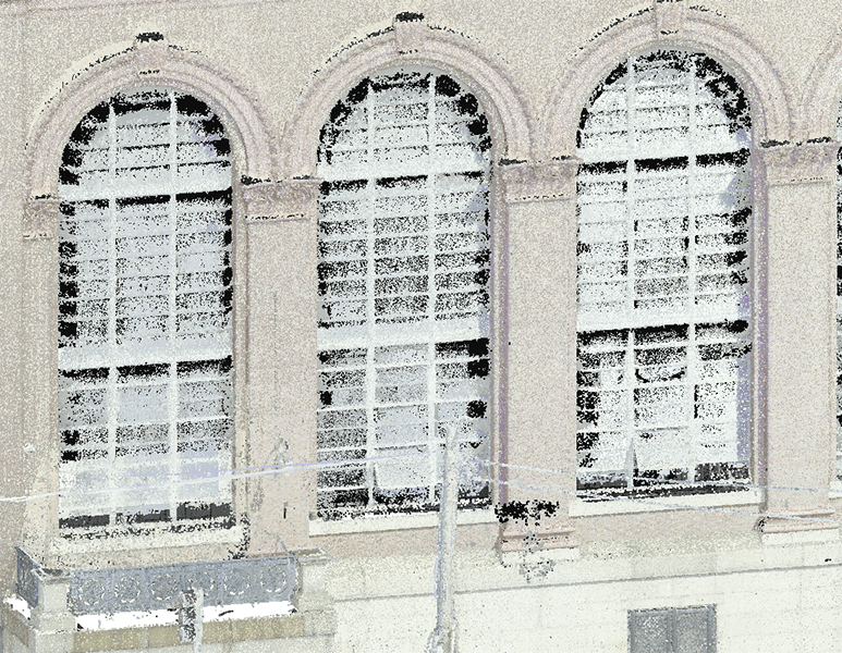
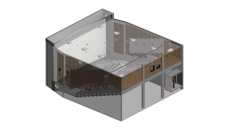
The historical building, which currently is used as a plant room for the distribution of different communications (such as electricity, water, etc.), required window replacement reconstruction. For these aims, a full laser scan of the exteriors of the building was provided, along with a fragmentary survey of the building’s interiors. A couple of stations of laser scanners were placed inside the building to acquire information about wall thicknesses only.

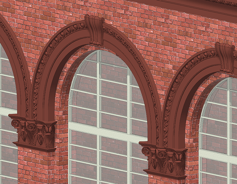
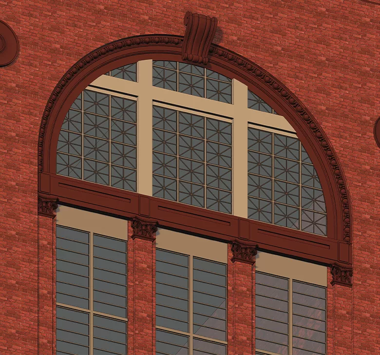
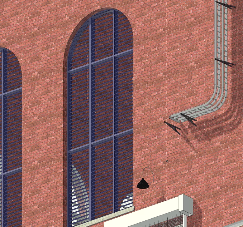
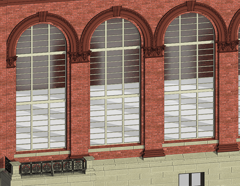
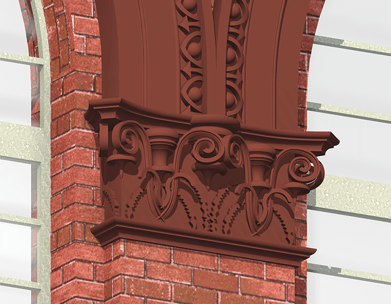
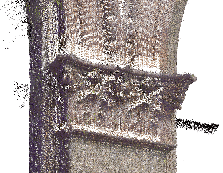
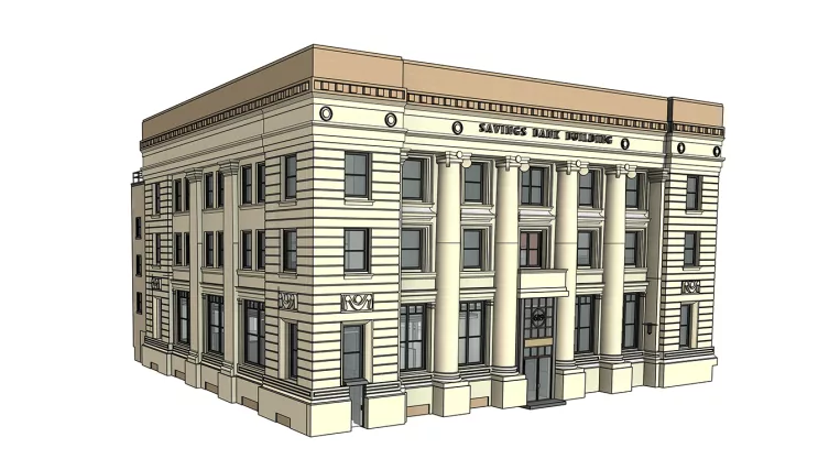
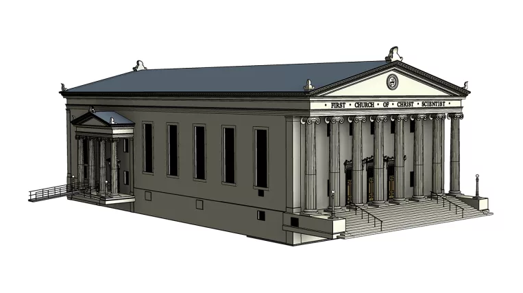
The request for a high level of detail in the exterior decoration elements made this project interesting in terms of architectural modeling.

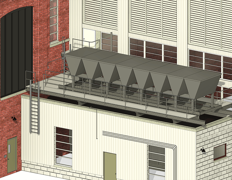
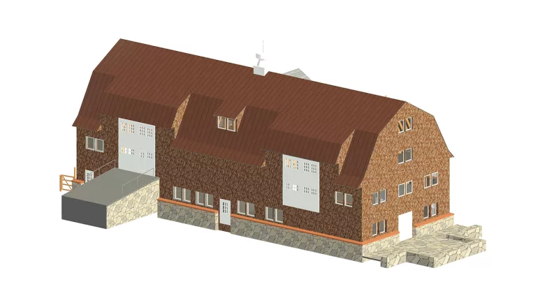
Scope of work: Detailed modeling of the building’s facades (50% historical, 50% industrial) for window replacement.

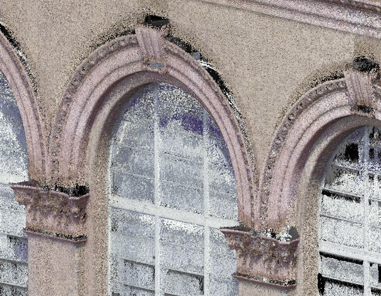
Input: Complete point cloud of the building’s exteriors (interiors provided for reference only).

Output: 3D Model at LOD 350.

Services: ARCHITECTURE, BIM, MEP
Subservices: Scan to BIM
Industry: Commercial
Object type: Historical
Tools used: Autodesk Revit, Autodesk ReCap
Share:
Project stages
1. Receiving input
2. Analyzing the input: requesting additional information and selecting the optimal team structure
3. Creating the architectural shell of the building, comprising walls and roofs
4. Modeling all insert elements, such as windows and doors, in detail
5. Adding detailed exterior embellishments
6. Providing project support
1

The main requirements

The client requested 2 main features to be incorporated into the model:

  • The unification of similar elements and the rounding of the project’s dimensions. All the similar elements were thoroughly analyzed before modeling to pick up an optimal configuration that would match the best of all the instances of these elements while staying within the set tolerance of modeling. Also, all the distances between elements were kept repetitive and rounded. The minimal allowable fraction was 1/4″, and all smaller or uneven fractions were avoided. What was admissible is that all these roundings were kept directly in the model, not only by the rounding function of dimensions. It can be seen as nothing special for design projects, but keeping all these restrictions in an as-built model adds up to the work to do greatly.
Point cloud vs Model

The main requirements

  • In terms of keeping the model as flexible as possible, the client asked to keep all the elements as separately selectable and editable items in the model. It means that all the architectural embellishments around the window should not be contained in the window family. This will allow setting different phases and removing objects individually to make the process of reconstruction simulation more detailed and understandable. For the aim of flexibility, all the separate layers of walls also were added as separate elements, avoiding stacked wall tools (pilasters and granite socle were added taking into account this requirement). Along with this, the usage of the “model-in-place” tool was excluded, and all the profiles were added using “profile” families instead of creating sketches directly in the profile editor. This keeps the model smart and easily adjustable.
1
Point cloud vs Model
1

MEP component

Also, all the identifiable facades’ MEP elements were requested to be added. It included:

  • Cable trays and their support elements;
  • Thick conduits;
  • Exterior lighting;
  • Rooftop equipment;
  • Piping and ducts that go out of the building;
  • Other small elements.

The combination of detailed architectural modeling with MEP elements included provides a comprehensive understanding of the facade’s configuration for further reconstruction works.

Point cloud vs Model
Benefits
Detailed model for reconstruction simulation
Flexible approach to modeling for handing over the model for further work
Unification of all existing elements while keeping the precision of modeling
Tools used
1
Autodesk Revit
1
Autodesk ReCap
view project view more view photos