Search...
Overview

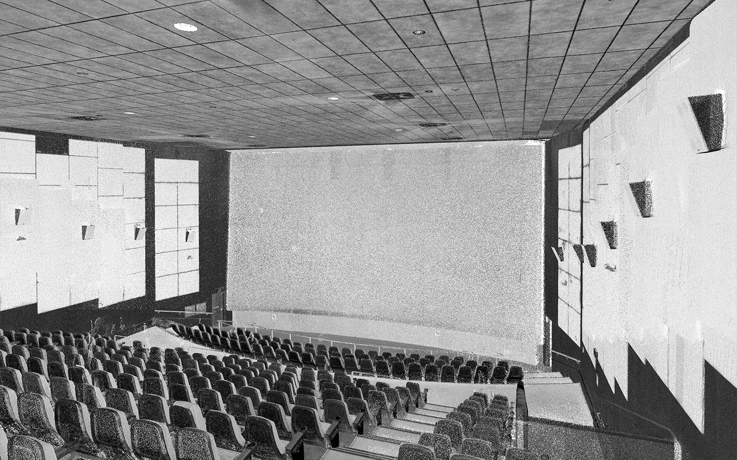
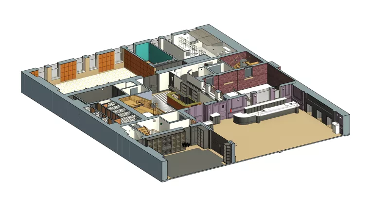
The client has expressed the desire to replace all the cinema equipment with modern ones. To achieve this aim, the existing as-built drawings were requested to analyze the hall space, existing equipment, etc. The model was received as a byproduct of drawing creation. The strategy of generating drawings based on the model was chosen to keep all the drawings well-coordinated and to avoid contradictions between them.

Scope of work: Modeling the interior space of a cinema hall, placing all cinema equipment, and creating a set of drawings.

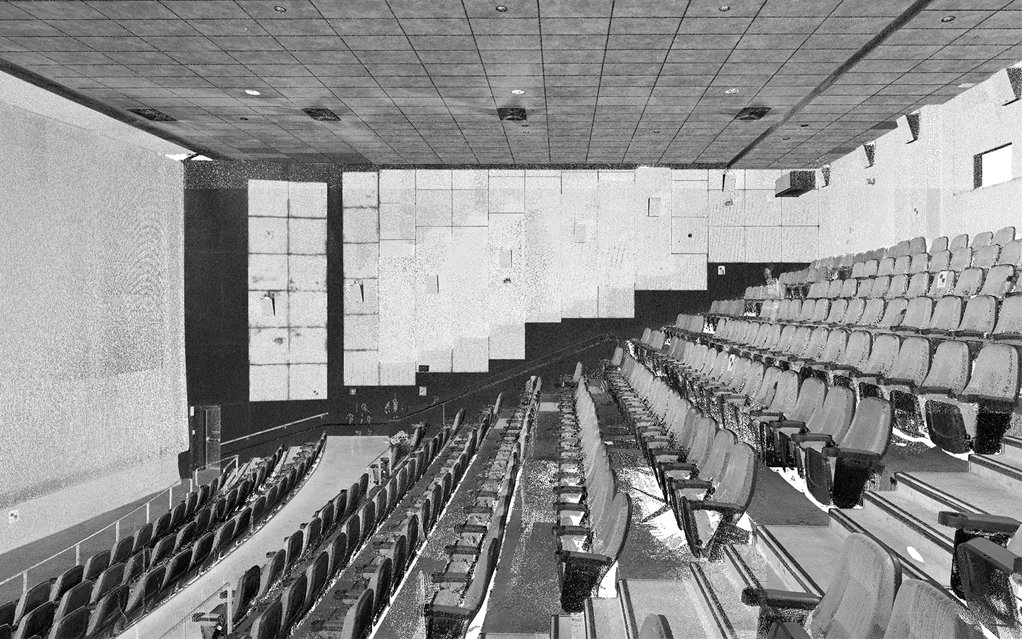
Input: Point cloud of cinema hall interiors.

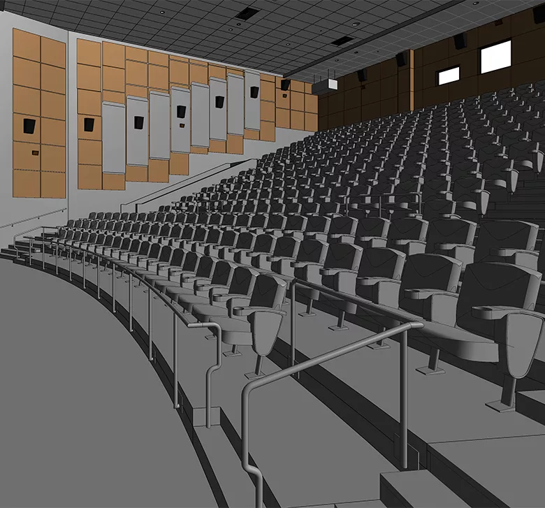
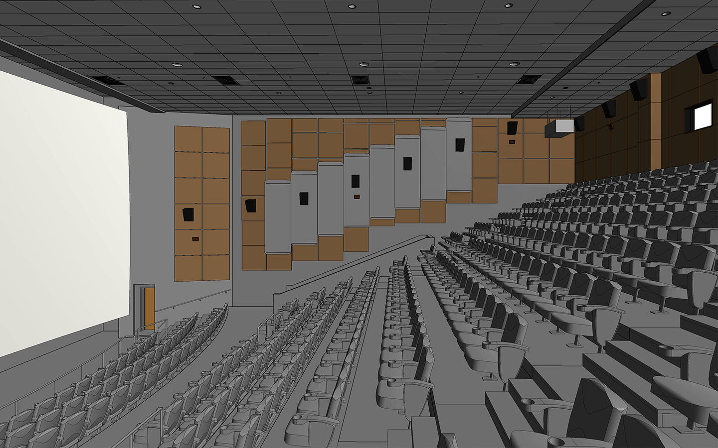
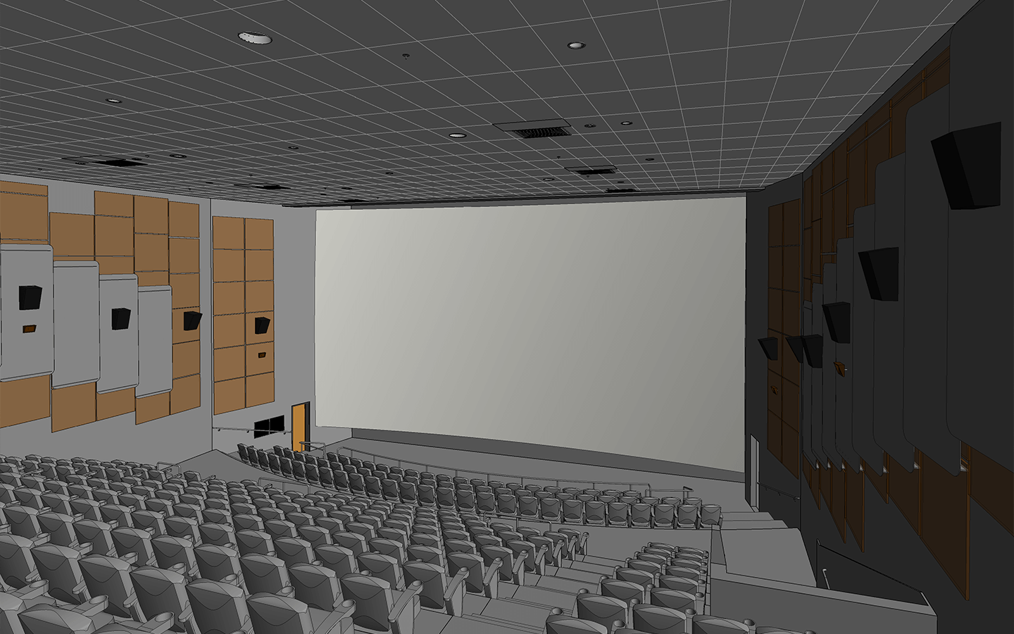
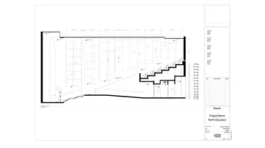
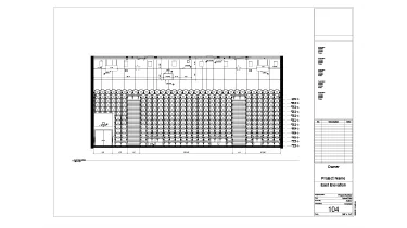
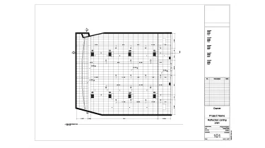
Output: 3D Model at LOD 300; Drawings (including floor plans, interior elevations, RCP, and sections).

Services: ARCHITECTURE, BIM, MEP
Subservices: Scan to BIM, As-built drawings
Industry: Commercial
Object type: Public
Area: 480 m² / 5170 ft²
Tools used: Autodesk Revit, Autodesk ReCap
Share:
Project stages
1. Receiving input
2. Analyzing the input, requesting additional information, and selecting the optimal team structure
3. Modeling the architectural shell of the movie hall
4. Populating the shell with all distinguishable equipment
5. Generating and annotating drawings
6. Providing project support
1

Object description

The auditorium of the movie hall has an area of approximately 5,200 square feet and a capacity of 360 seats. The walls of the hall are covered with sound-absorbing mats to protect the adjacent spaces from extra noise.

The entrance to the movie hall is concealed beneath the massing of the amphitheater’s steps, created for seating placement. The equipment was located along the entire perimeter of the walls and on the ceiling.

The main piece of equipment was a curved cinema screen, both in horizontal and vertical directions, located on the wall opposite the amphitheater’s stairs.

Point cloud vs Model
Scan-to-CAD vs Scan-to-BIM

Despite the initial request of the client to get only CAD drawings of the space, after analyzing the amount and diversity of the drawings from different projections, it was suggested by the ORIGIN team that we would create the complete 3D model based on a point cloud and then automatically generate all the graphical information needed for the drawings from the model created.

The main objectives to insist on 3D modeling were:

  • The number of drawings from different projections requested. For a single drawing, it’s more time-efficient to work directly with 2D and process the single section of the point cloud. The more drawings required, the more rational it is to use a 3D model as a base, because once a 3D model is developed, it’s easy to generate an infinite amount of drawings based on this model in a short time span;
  • Coordination of the drawings between themselves. The more drawings are created in 2D, the higher the chances to meet some discrepancies between different projections of single objects. With working in 3D, these potential issues are automatically eliminated.

The total timeline for the creation of the model and generation of the drawings on its basis didn’t exceed the time that would have been spent in the case of creating each separate drawing in 2D only. Despite the assumption that the volume of work for the creation of 3D seemed to take more time, this assumption is wrong since 3D models allow us to save tons of time on the drafting stage while simultaneously guaranteeing the high quality of the output.

Point cloud vs Model
Drawings

Click on preview to view high resolution PDF drawings

Benefits
Quick generation of a bunch of drawings based on the 3D geometry created
100% coordinated drawings that don't have any discrepancies between them
Decreasing production time with increasing output (3D model as a side product)
Tools used
1
Autodesk Revit
1
Autodesk ReCap
view project view more view photos