Search...
Overview

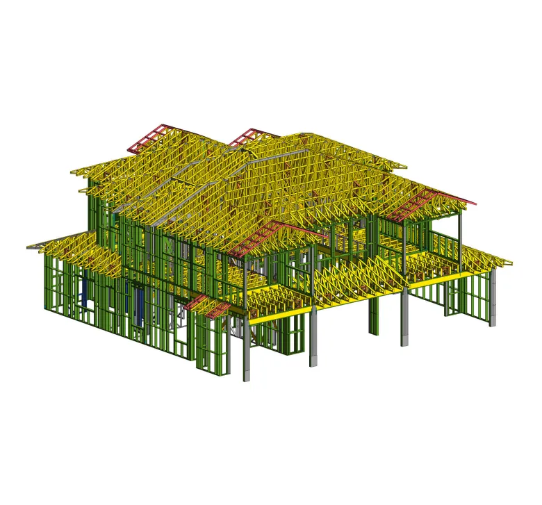
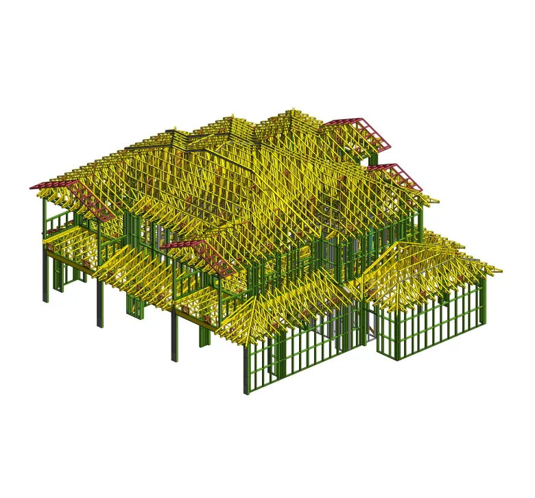
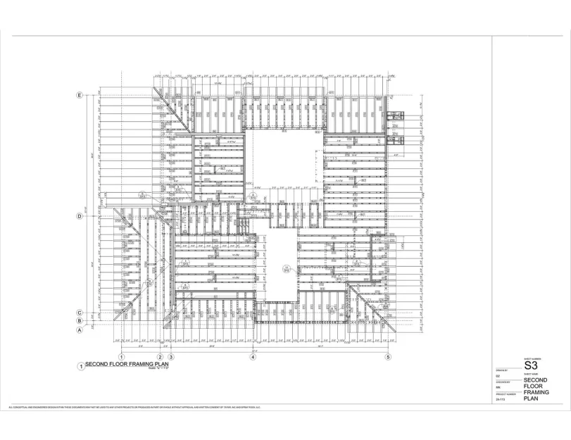
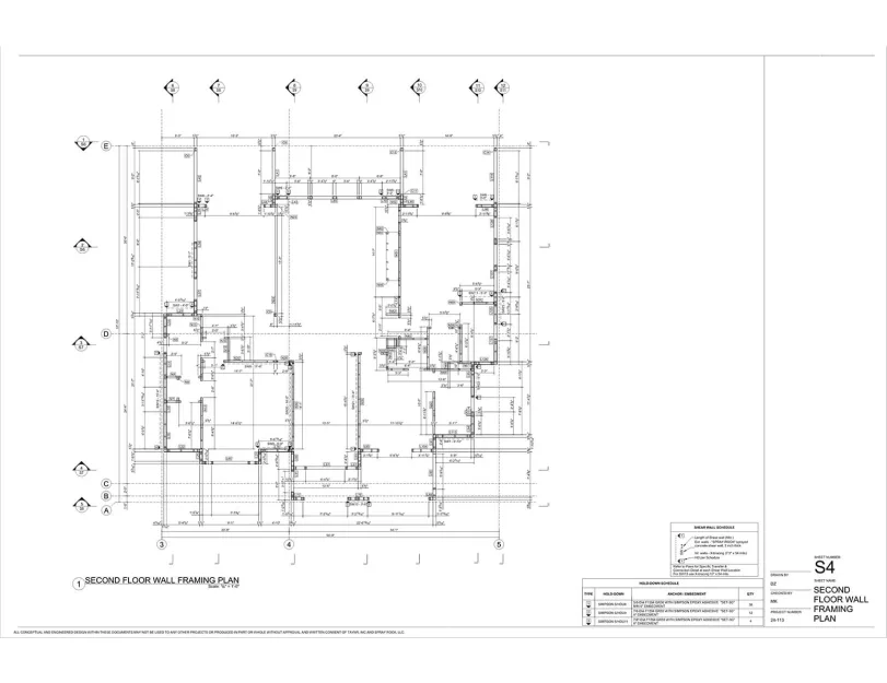
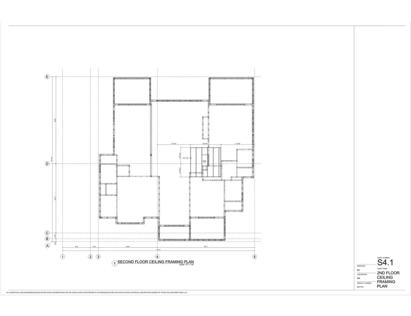
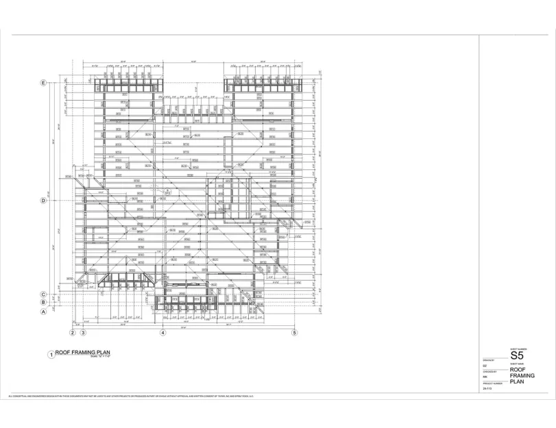
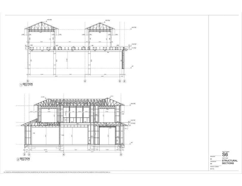
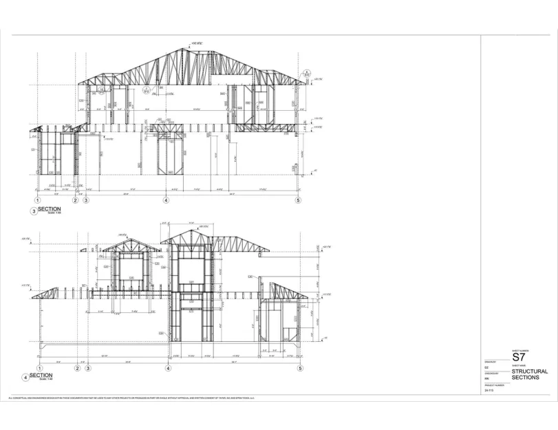
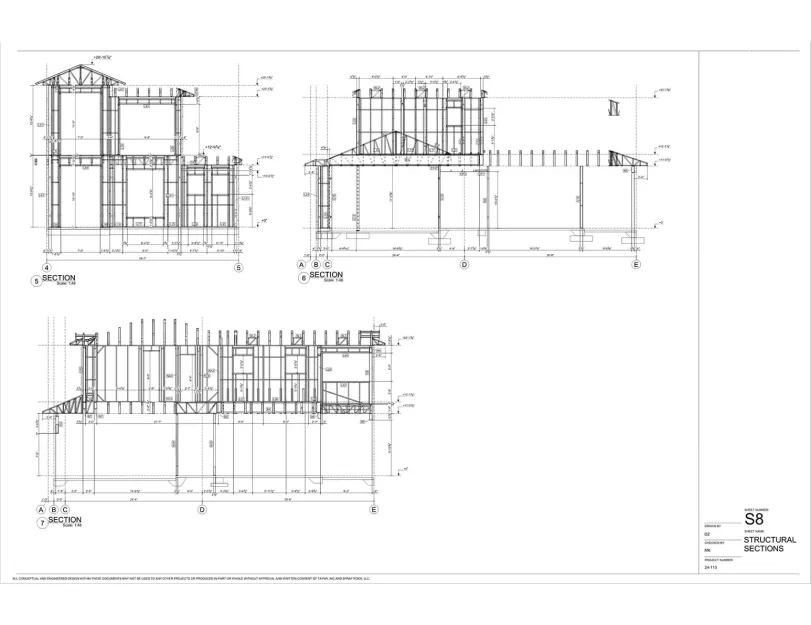
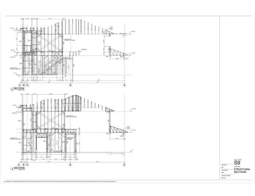
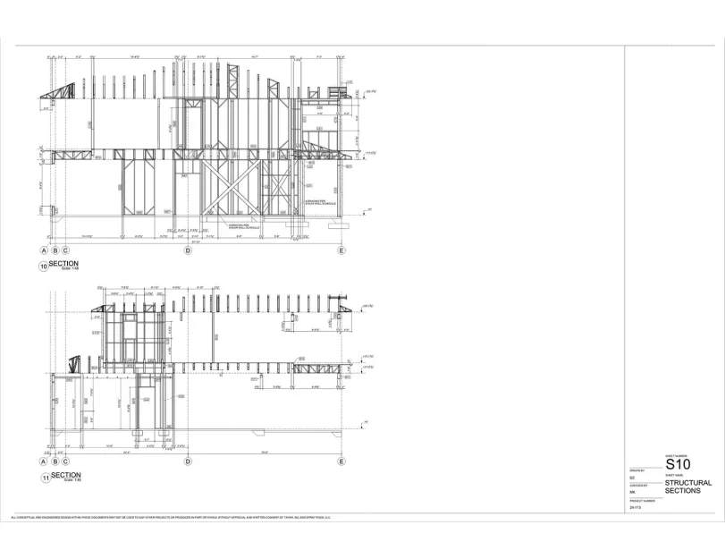
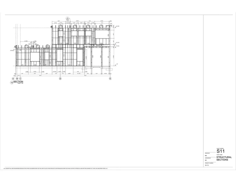
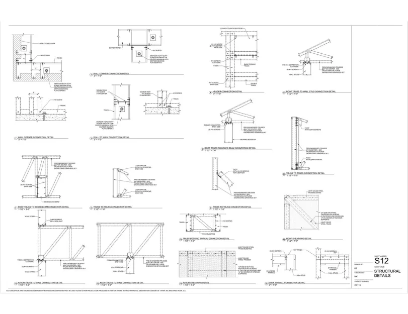
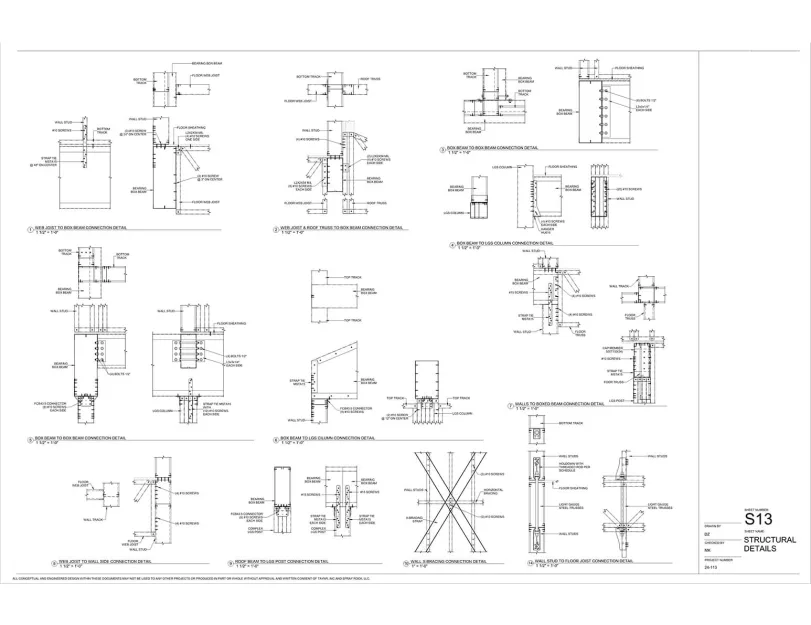
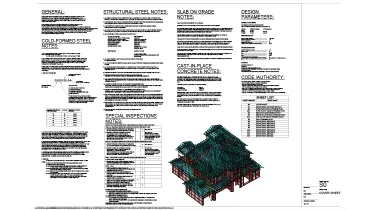
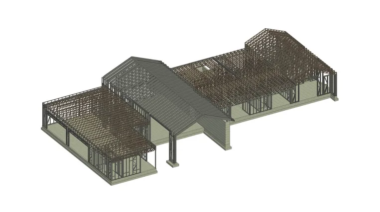
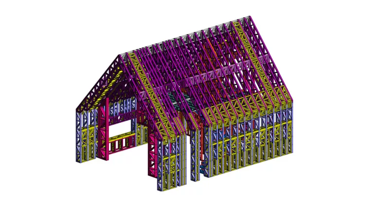
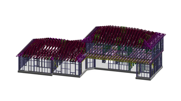
The project involved Revit modeling, Shop drawings, and CNC file generation for a spacious two-story building measuring 69′ × 58′ with a complex floor plan.

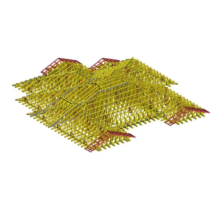
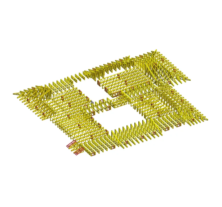
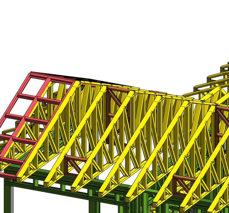
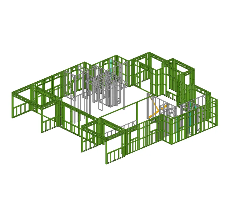
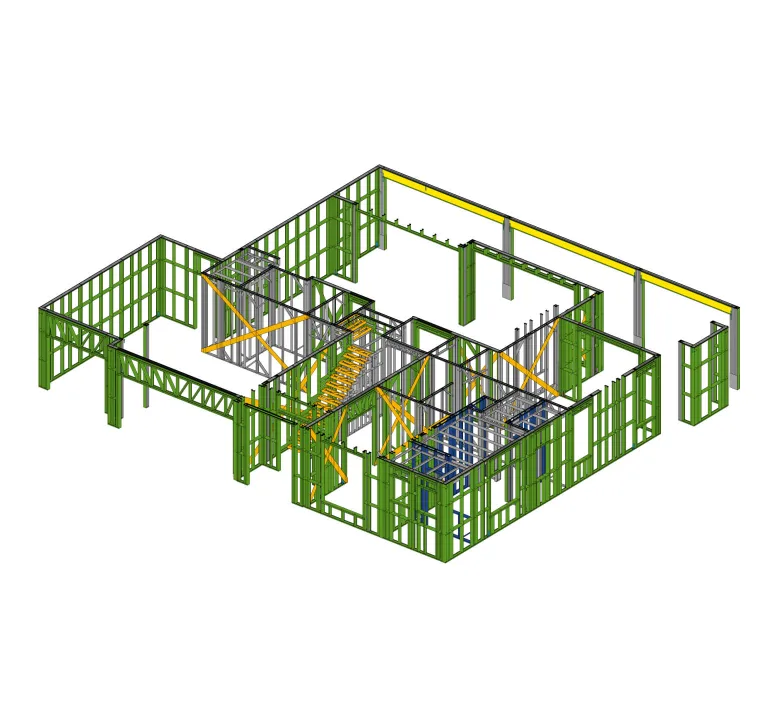
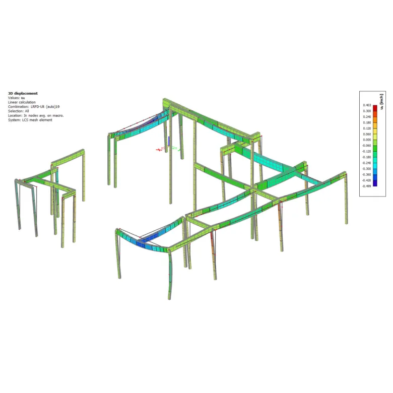
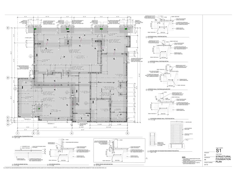
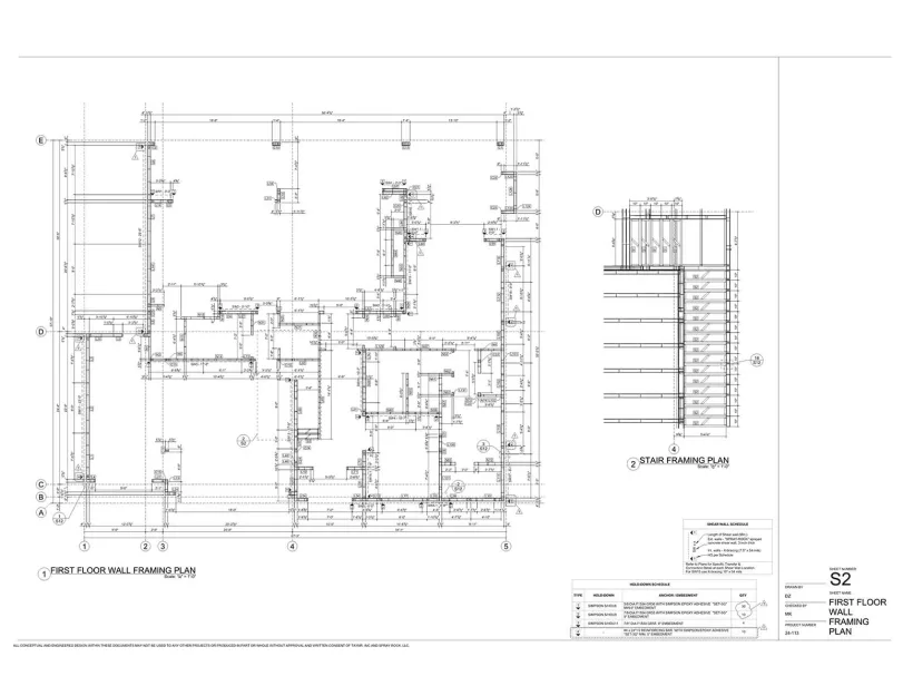
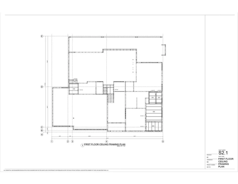
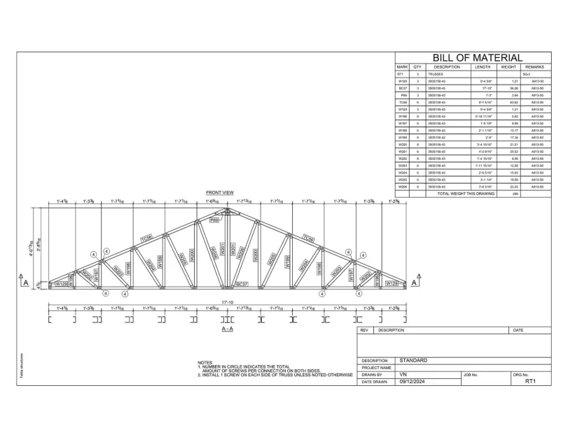
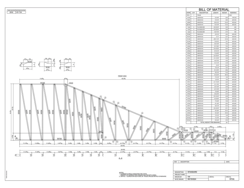
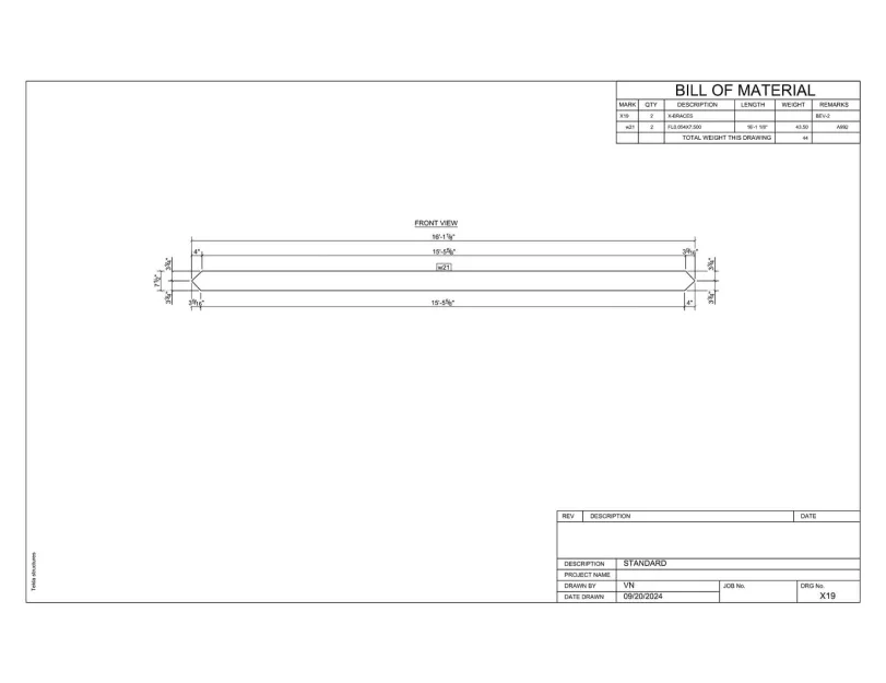
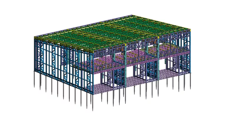
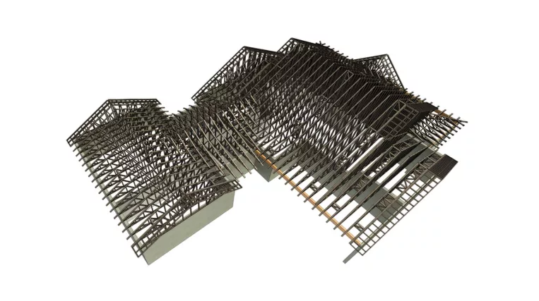
All building’s walls, floors, and roof trusses are designed in light-gauge steel. The uniqueness of the building lies in the second-floor walls, some of which are offset inward and supported by the floor system, along with a combination of vertical X-bracing straps and a sprayed concrete shear wall. The foundation utilized a slab-on-grade foundation, with additional footings provided where LGS columns require support.

As a project result, the ORIGIN team produced a spatial model, providing a comprehensive 3D analytical representation of the structure. In addition, the design follows the requirements of the 2021 Edition of the International Building Code, as listed in the code/authority references below.

Input: Architectural drawings set

Project deliverables:

  • Revit model;
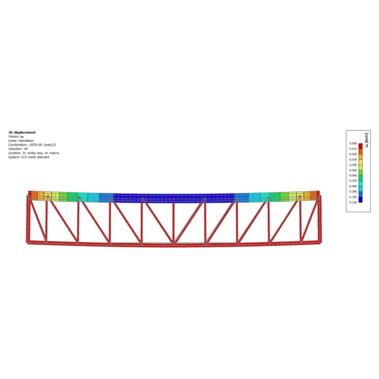
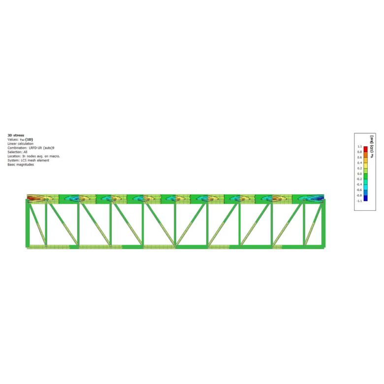
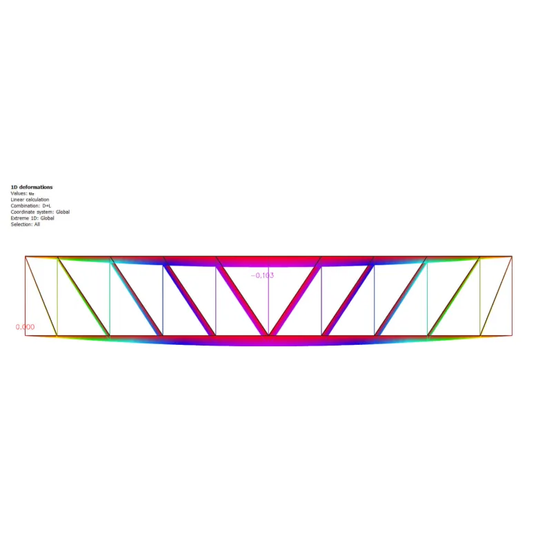
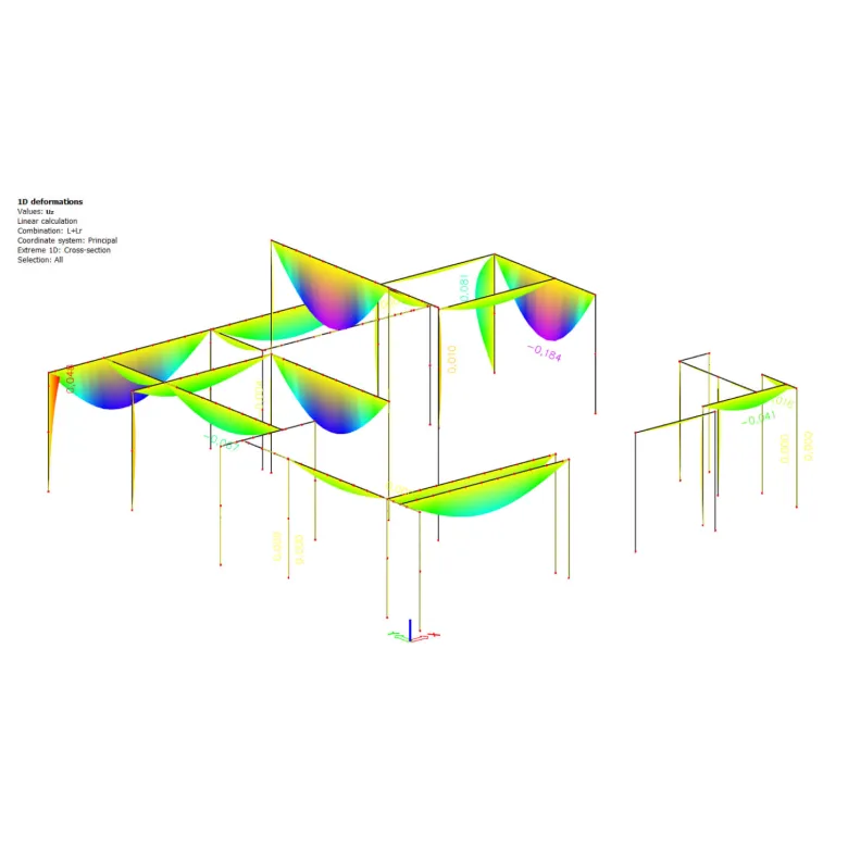
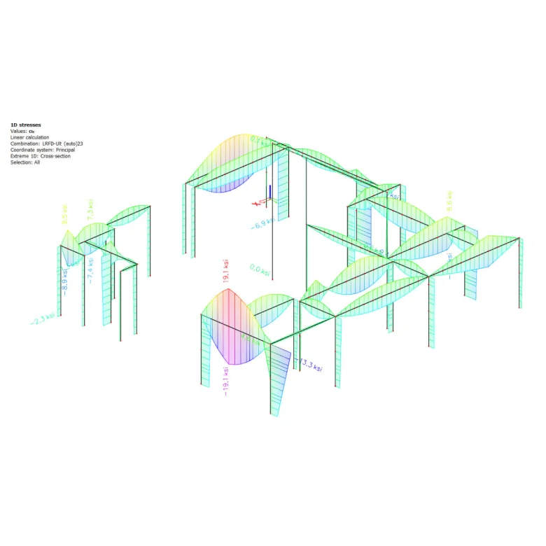
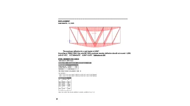
  • Structural analysis report;
  • Structural drawings set;
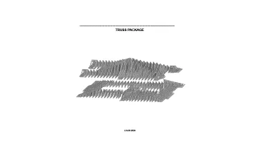
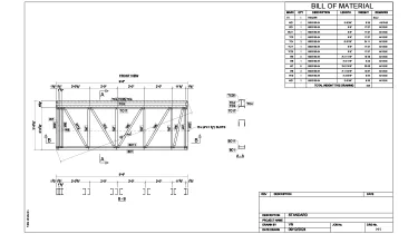
  • Shop drawings;
  • CNC files.
Category: STRUCTURE
Services:Hot-rolled steel design and detailing, Construction drawings, Prefabricated construction services, LGSF design and detailing, Hot-rolled steel framing, Cold-formed steel framing, Fabrication/Installation drawings, Concrete foundations, Wood framing
Industry:Residential
Object type:Single-family home
Area:506 m² / 5450 ft²
Tools used:Autodesk Revit, Strucsoft MWF Advanced Metal, SCIA Engineer, Tekla Tedds, Tekla Structures
Share:
Project stages
1. Revit model creation
2. Structural modeling
3. Structural analysis
4. Structural drawings creation
5. CNC files and shop drawings production
Code/Authority List:
  • 2023 Florida building code;
  • 2021 Edition of the International Building Code;
  • ASCE 7-16;
  • Steel design: AISC 360-16: LRFD Specification for Structural Steel Buildings;
  • Seismic AISC 341-16 Seismic Provisions for Structural Steel Buildings;
  • Concrete: Reinforced Concrete Design Handbook (ACI);
  • Ultimate Strength Design Handbook (ACI).
Revit host model creation

Starting off the project, ORIGIN began the process with a thorough review of the architectural drawings, which served as the foundation for a conceptual structural framework. At this stage, it was essential to verify the structural viability of the architectural layout. Any issues identified were communicated to the architect for revision.

Next, the ORIGIN team converted the PDF architectural drawings into detailed Revit models, incorporating elements such as foundations, floors, roofs, and walls. These models provided the foundation for the subsequent LGS framing design.

1
1
1
1
1
1
1

Structural model creation

Once the Revit model was completed, it was exported to Tekla Structures to generate wall framing and other components using LGS extensions.

After that, the completed framing was then re-imported into Revit, where the LGS model was finalized by integrating roof trusses with the support of the MWF plugin. Thanks to this automation, we were able to optimize model accuracy, reduce manual modeling time, and deliver a fully coordinated, construction-ready structural model.

Structural calculations

After completing the preliminary structural model, we proceeded with a full structural analysis of the entire building using the following technologies:

  • Scia Engineer software – for analyzing the LGS framing system;
  • Excel and Mathcad spreadsheets – when doing calculations for the masonry walls and foundation.

As a result, the ORIGIN team delivered a complete structural report, including all analysis outcomes and supporting calculations. See them listed at the end of this page.

1
1
1
1
1
1
1
Structural drawings production

After LGS framing was verified through calculations, the next stage involved generating Revit views. They included plans, sections, elevations, and other key details. While Revit views remained the main source for architectural coordination and overall documentation, some drawings were also exported directly from Tekla Structures to ensure that shop drawings and framing layouts match.

The drawing production process was fast and straightforward, since the structural model was already complete and there was no need for manual drafting. This way, we only needed to add dimensions, text annotations, and supplementary notes.

The finalized plans were then submitted to the building department for approval.

Structural drawings
CNC files and shop drawings production

Upon plan approval, we proceeded to the final stage — producing the LGS panels.

This involved two main steps:

Stage 1 — Generating CNC files from the Tekla model and giving them to the client to load them into the Howick rollformer to fabricate the individual LGS members.

Stage 2 — Assembling the panels using these members, guided by detailed shop drawings for each panel. Every component was clearly labeled and dimensioned to ensure accurate assembly

Shop drawings
Drawings

Click on preview to view high-resolution PDF drawings

Benefits
Eliminated risks of on-site installation issues thanks to the precise alignment of LGS framing with the building geometry
The possibility of early clash detection with other systems through a BIM-based LGS model
Colossal manufacturing time savings from CNC export and rollformer-based panel production
Tools used
1
Autodesk Revit
1
Strucsoft MWF Advanced Metal
1
SCIA Engineer
1
Tekla Tedds
1
Tekla Structures
view project view more view photos