Search...
Overview

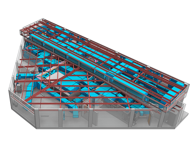
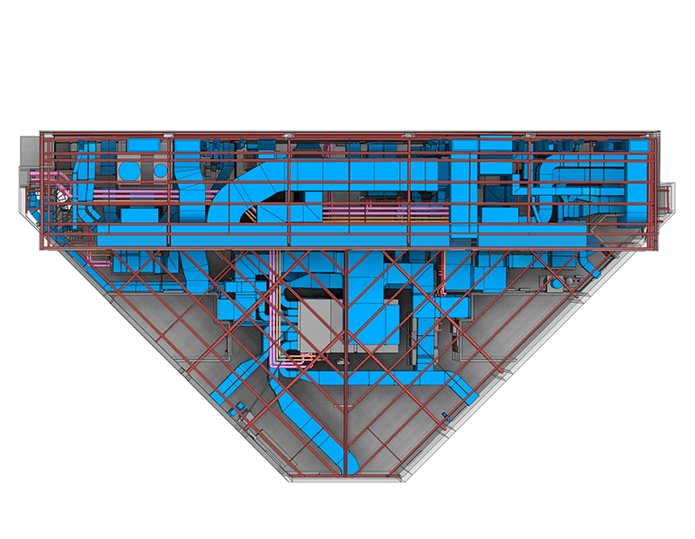
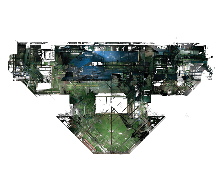
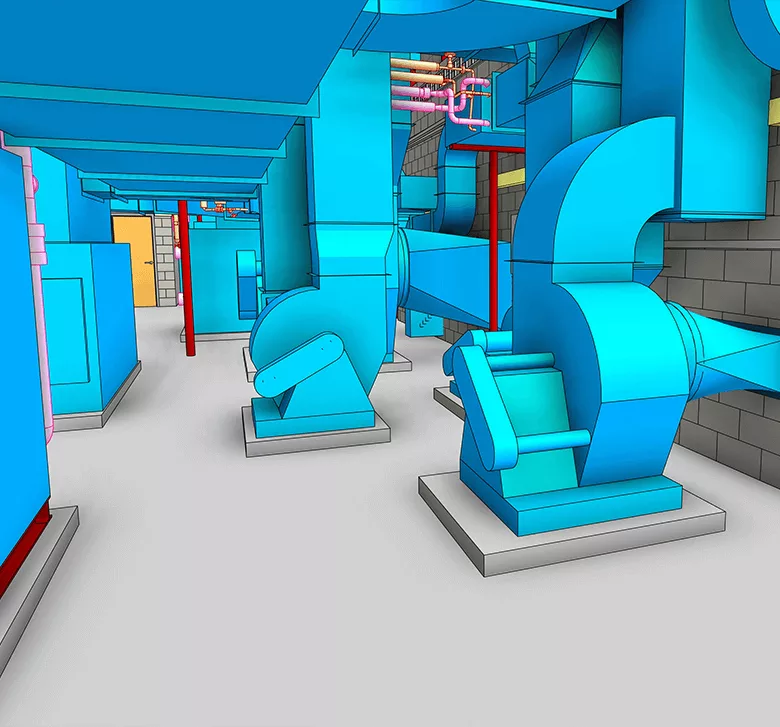
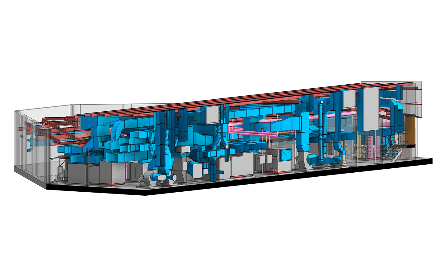
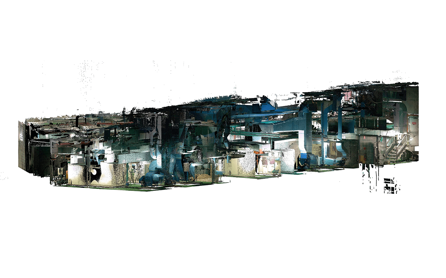
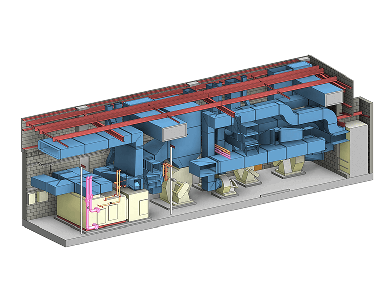
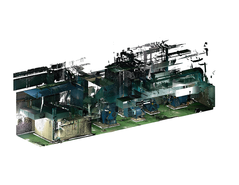
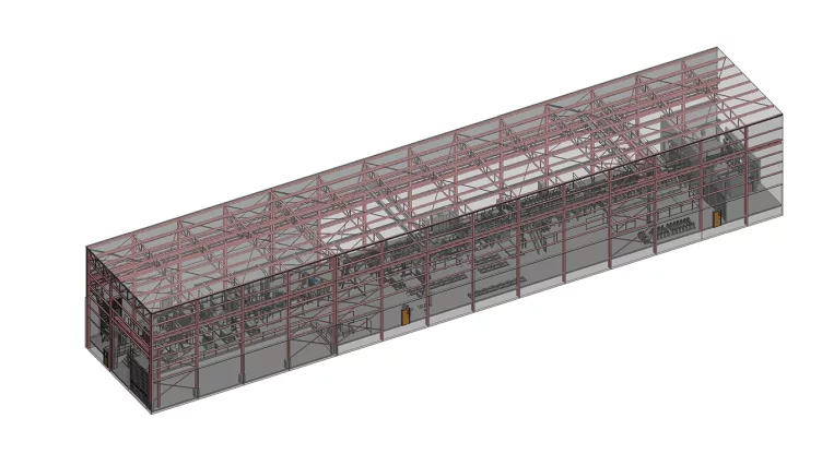
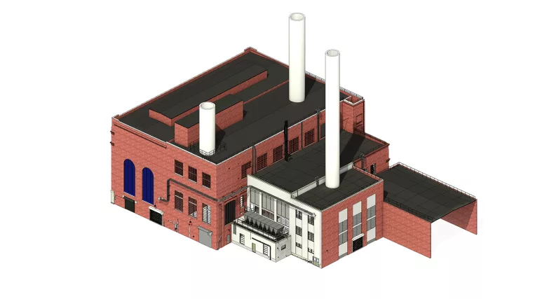
The client requested the modeling of three large and identically sized and shaped plant rooms, constructed for hospital service.

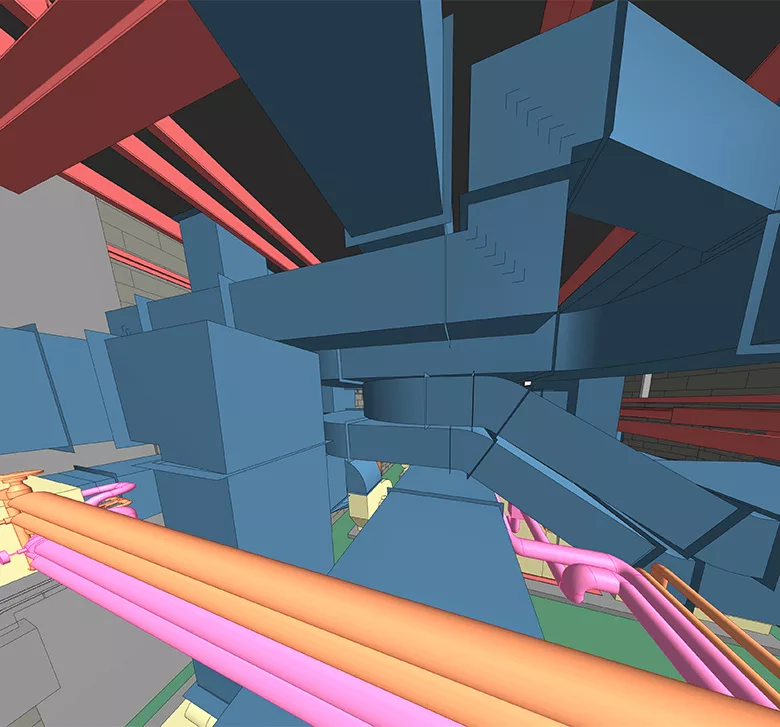
Plant rooms, sometimes referred to as mechanical rooms or boiler rooms, are spaces dedicated to housing the equipment required for various building services, such as ventilation, electrical distribution, water, and more.

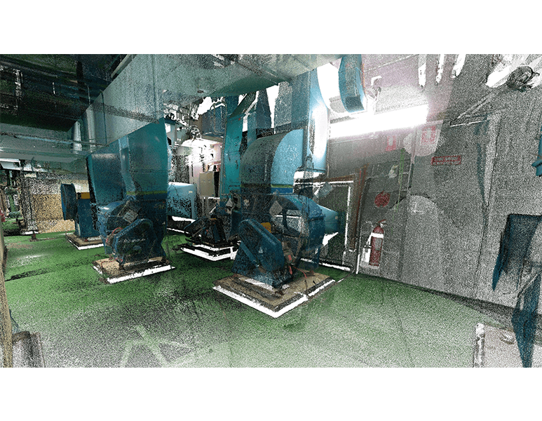
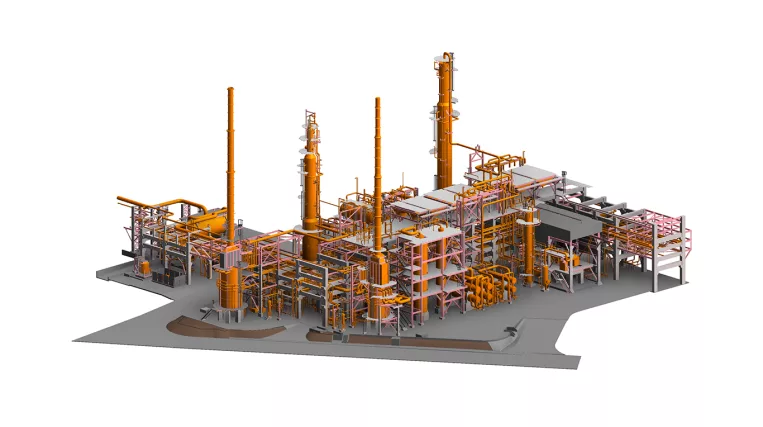
The size of a plant room is usually proportional to the building’s size and type. Large structures may have several plant rooms (as in our hospital), some occupying one or more stories, and others with specific functions, such as battery rooms, transformer rooms, boiler rooms, etc.

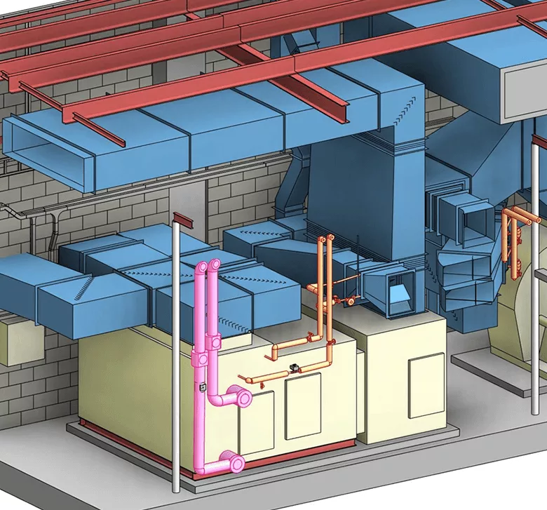
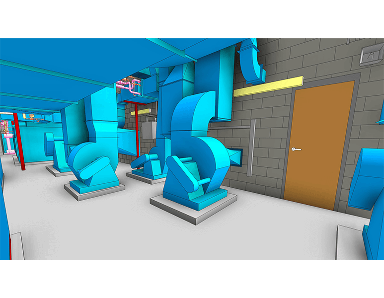
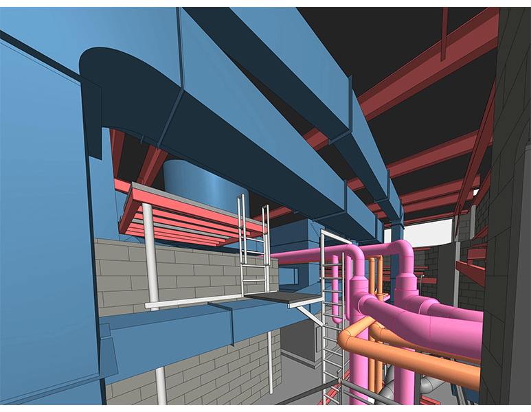
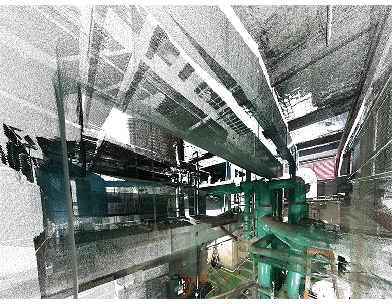
The plant rooms in this project predominantly contained duct systems, with a minimal amount of piping.

Scope of work: Precise modeling of three large Mechanical Plant Rooms, each replete with numerous ducts, pipes, and equipment.

Input: Comprehensive Point Cloud of the interiors for the three identical plant rooms. Photos of areas with inadequate scanning were provided upon request.

Output: 3D Model of the plant rooms at LOD 300.

Services: MEP, BIM
Subservices: Scan to BIM
Industry: Industrial
Object type: HVAC rooms
Area: 2000 m² / 21530 ft²
Tools used: Autodesk Revit, Autodesk ReCap
Share:
Project stages
1. Receiving input
2. Analyzing the input: requesting additional information and selecting the optimal team structure
3. Creating the basic architectural/structural shell to house the systems
4. Modeling the systems, including pipes and ventilation equipment
5. Adding pipes complete with all identifiable fittings
6. Implementing a quality control process
7. Providing project support
1

Challenges on the project

The main challenge was the density of the mounted elements (ducts, pipes, equipment). The further the elements were from the scanner, the higher the probability of obstruction. It was common for the team to recreate the configuration of duct trajectories or supporting beams using only fragmentary scraps of the points captured.

When recreation was impossible, additional photos from the client (who had access to the building site) were requested to ensure accurate modeling.

Furthermore, the lighting of the scanned rooms played a crucial role in the simplicity of processing and the project’s success. Elements placed in darkened areas were challenging to identify, and their modeling took longer and could be less precise.

Point cloud vs Model

Ventilation systems

Ductwork was modeled using the fabrication tool in Revit. The standard fabrication libraries contain a wide range of all needed ductwork segments, such as:

  • Transitions
  • Elbows
  • Taps
  • Tees
  • Shoes
  • Offset segments, etc.

These include different cross-sections and a flexible system of parameters, allowing for shapes that perfectly match the Point Cloud.

These tools enable the assembly of ductwork similar to a Lego set. All mechanical equipment, such as furnaces and fans, was modeled with a low level of detail using the model-in-place tool.

1
Point cloud vs Model
1

Piping systems

Piping was modeled using standard Revit piping tools, considering piping insulation where thickness could be identified. All distinguishable pipe accessories were also placed on the pipeline. The systems were slightly “idealized,” meaning that when pipes had deflections or deviations from orthogonal directions, they were modeled as close to the cloud as possible while preserving straightness. This approach helped maintain system elements’ connectivity in the Revit environment, making them easily selectable as a whole system through the “tab” button.

Point cloud vs Model
Benefits
A model that includes all the systems present in the building
The opportunity to work with accessible space for the installation of new equipment or reconstruction
Accessible clash detection of new elements with existing ones during the design stage
Tools used
1
Autodesk Revit
1
Autodesk ReCap
view project view more view photos