Search...
Overview

The client specializes in capturing infrastructure objects to create digital models, extracting real textures from photos, and applying them to the model. This process serves as vital documentation for identifying damages like cracks, corrosion, etc. Based on these models, building inspection reports are generated, and further plans for reconstruction and maintenance are developed.

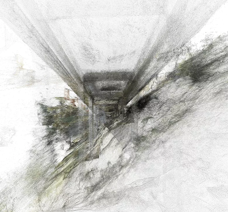
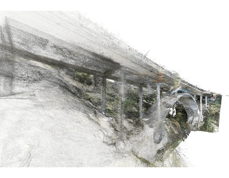
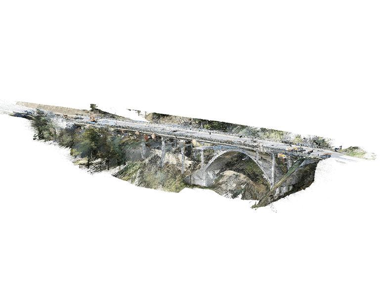
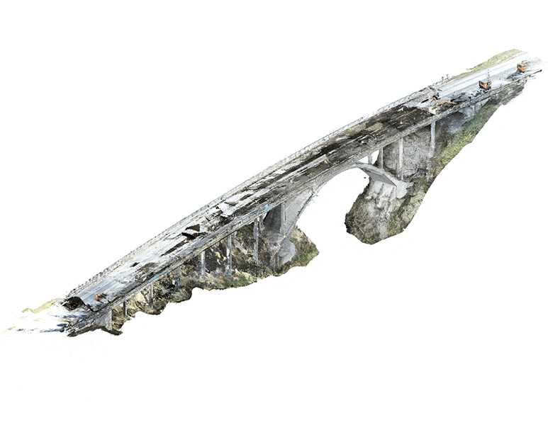
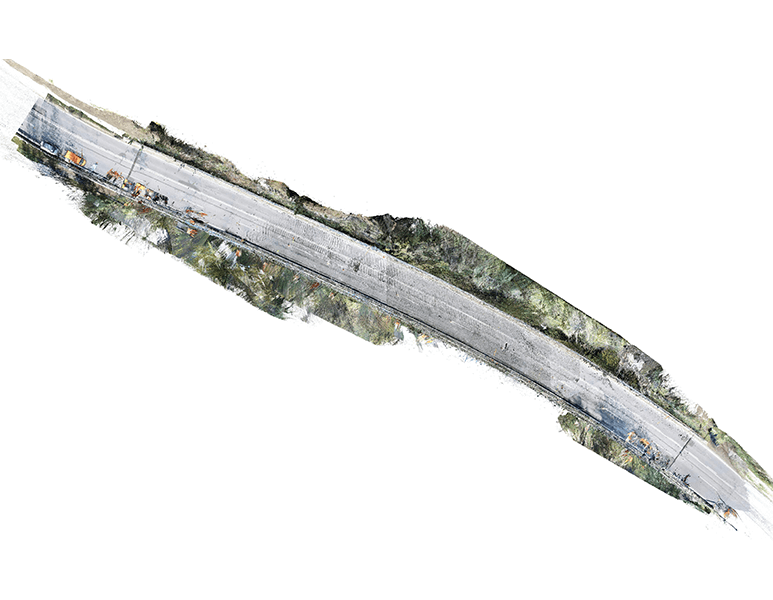
The client employs photogrammetry technology based on drone-taken photos, particularly chosen for its ability to access low-accessibility areas compared to standard scanners or digital cameras.

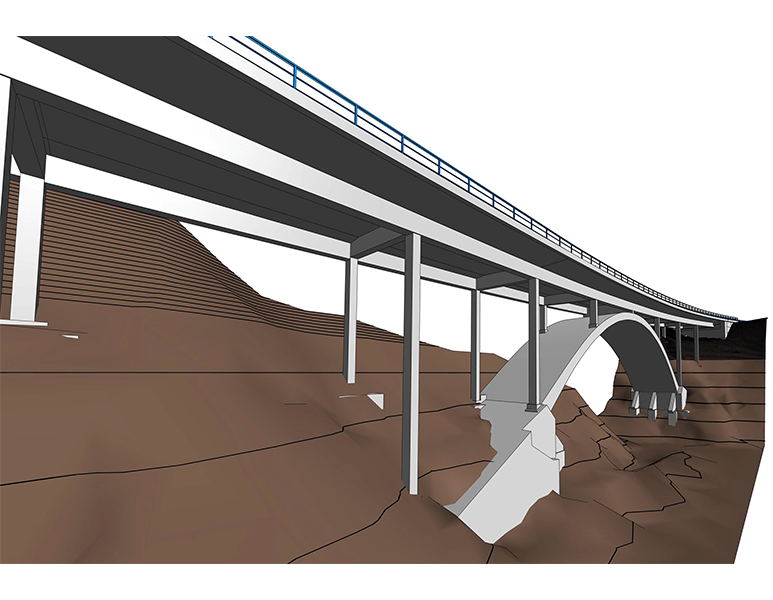
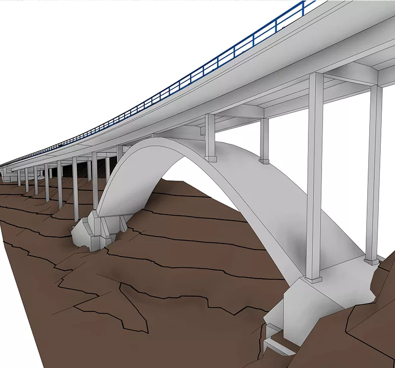
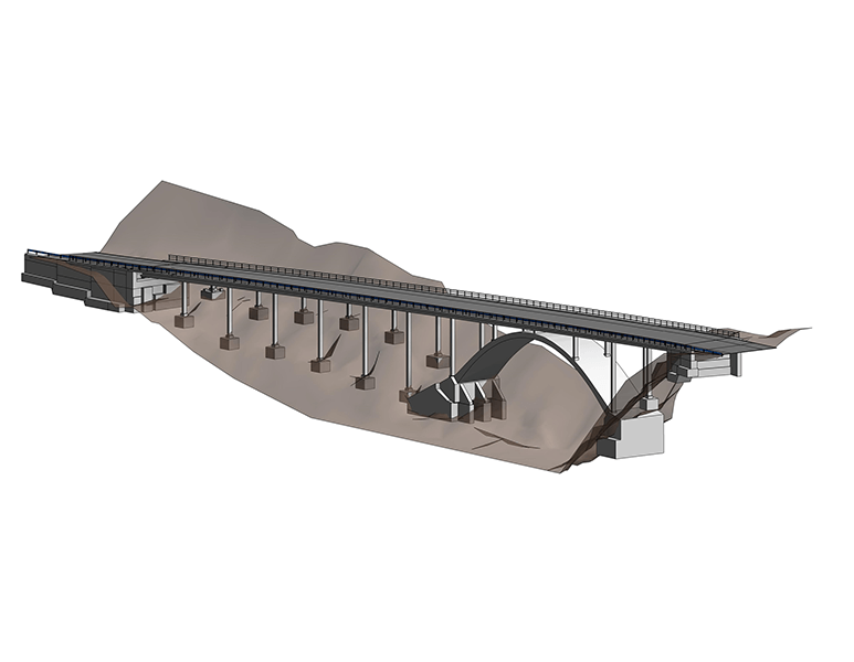
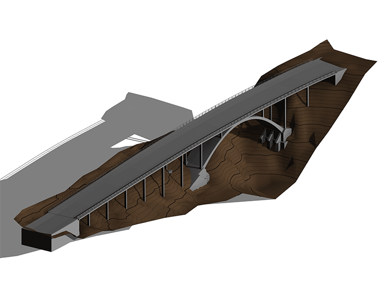
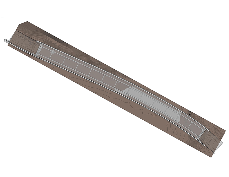
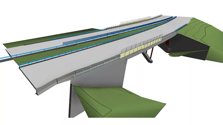
Scope of work: Precise modeling of the concrete arch bridge and the adjacent ground surface.

Input: Full Point Cloud of the bridge and adjacent area obtained through photogrammetry (drone capture).

Output: 3D Model of the bridge at LOD300.

Services: BIM, STRUCTURE
Subservices: Scan to BIM
Industry: Infrastructure
Object type: Bridges
Area: 200 m / 2160 ft
Tools used: Autodesk Revit, Autodesk ReCap
Share:
Project stages
1. Receiving input
2. Analyzing the input: requesting additional information and selecting the optimal team structure
3. Preparation for modeling: constructing a network of reference planes for bridge segmentation
4. Modeling the bridge surface and its supports
5. Adding all identifiable MEP elements
6. Implementing a quality control process
7. Providing project support
1

Challenges on the project

The project’s main challenges were rooted in the use of drones to capture point cloud data. Although this method offers advantages like accessibility to remote locations and cost efficiency, the received data is often quite noisy. Points may not create perfectly distinguishable surfaces and can be scattered with some inaccuracy, demanding extra effort from the team to process.

Additionally, issues like doubling or tripling the point cloud data with offsets relative to one another often occur. Solutions involve requesting reprocessing from the data provider or manually analyzing the data, but the latter cannot guarantee accuracy.

Point cloud vs Model

Modeling features

Unlike standard buildings, bridges usually don’t have orthogonal geometry. They might be curved in plan view and have elevation changes in side view, making classical Revit tools not fully suitable for bridge surface modeling.

The team developed a suitable method by creating cross-section outlines with a specific step in sectioning. Using the mass tool, they created smooth curved objects through the previously drawn cross-sections. The result is a precise model of a curved element, facilitating the application of textures.

1
Point cloud vs Model
General requirements

To accomplish the project’s goals, the team needed to follow specific requirements:

  • All railing separate elements had to match their real location perfectly for the correct placement of textures extracted from photos. Complexities arose when post placements lost regularity, requiring manual rail alignment adjustments for each location;
  • Elements like edge beams, road surface, and deck needed to be modeled as separate elements with perfect adjacency (no gaps allowed). Internal bridge structure, undefined by point cloud alone, required sketches agreed upon with the client before modeling;
  • Some projects provided drawings, and the team’s task was to combine model information from both point cloud and hidden constructions detailed in the drawings (e.g., abutment made of separate block structures, bearing piles buried underground, etc.);
  • All model elements for further work had to be transferred to .ifc format.
Point cloud vs Model
Benefits
Utilization of advanced tools in Revit for modeling curved elements
Integration of data received from the point cloud and provided drawings
Precise modeling for the application of real-condition textures
Used Tools
1
Autodesk Revit
1
Autodesk ReCap
view project view more view photos