Search...
Overview

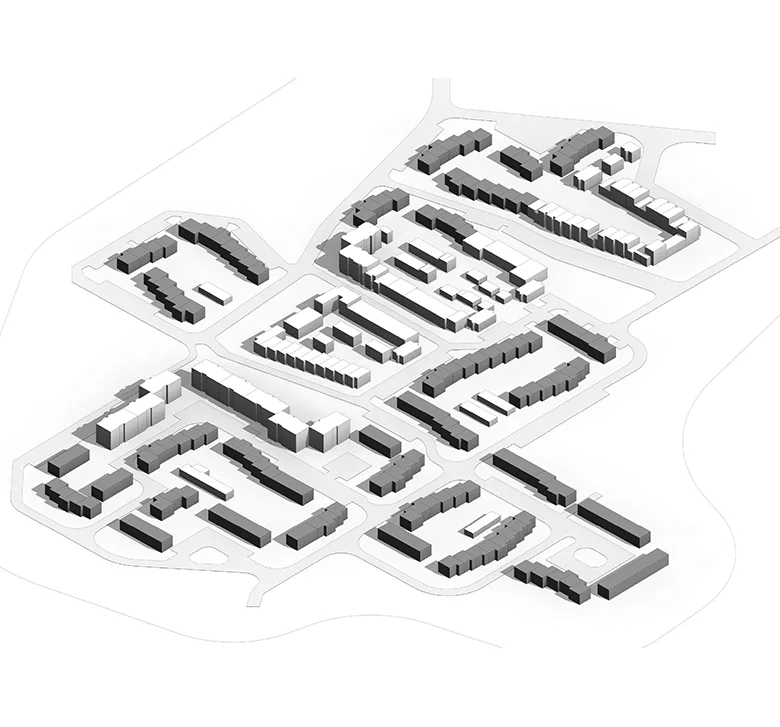
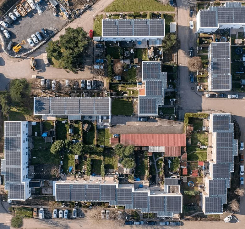
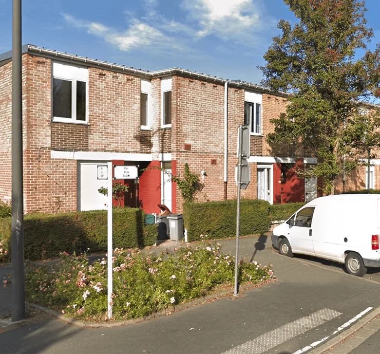
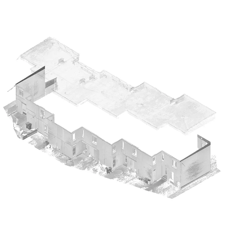
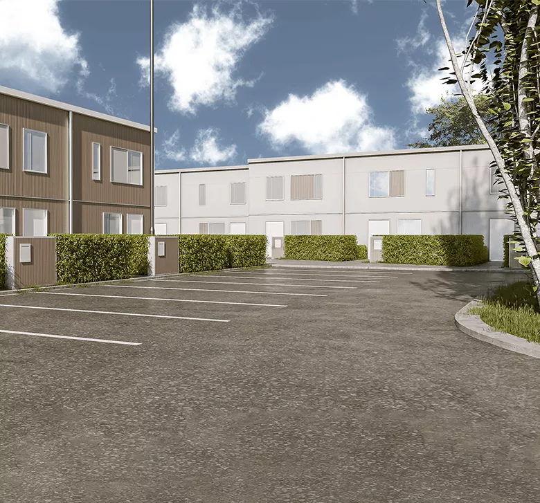
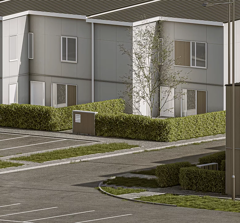
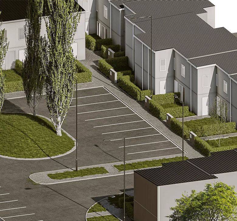
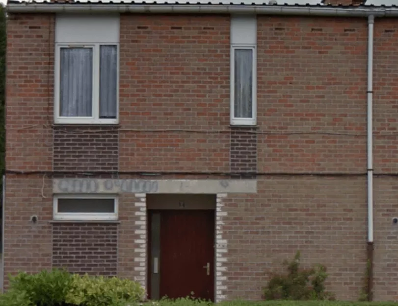
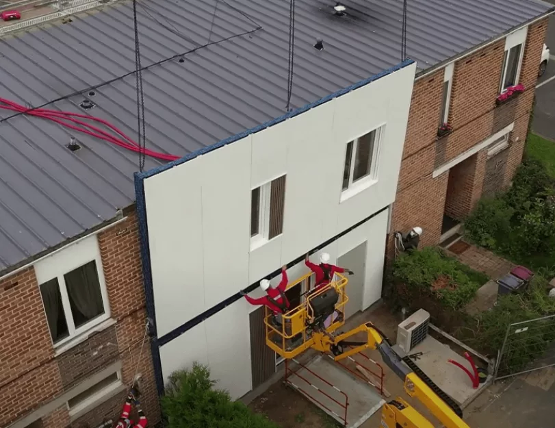
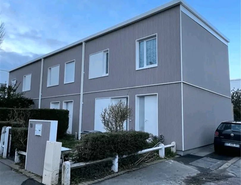
The property consists of 30 blocks of houses from the 1960s. Each block is composed of a couple of houses (a total of 160 houses). Our client’s goal was to promote the energy efficiency of these houses by adding extra insulation to exterior walls and roofs.

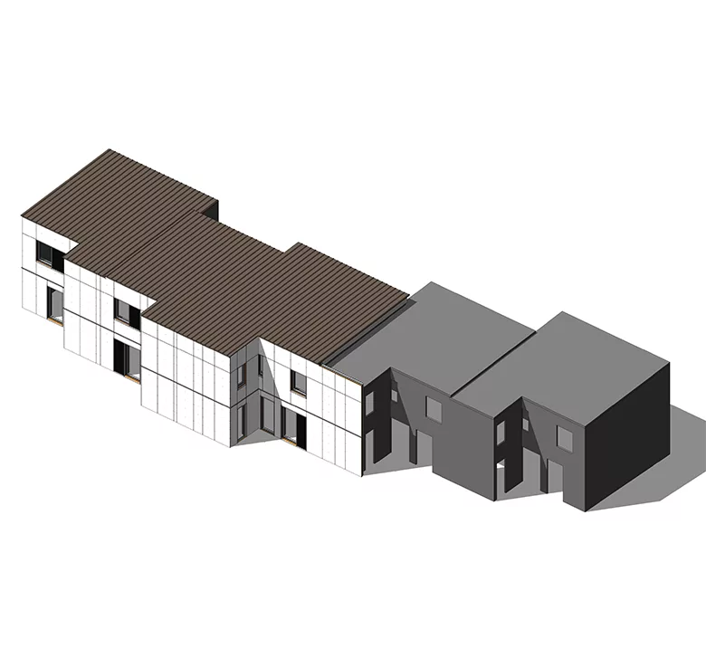
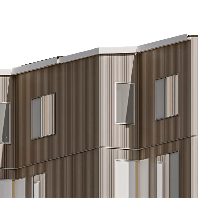
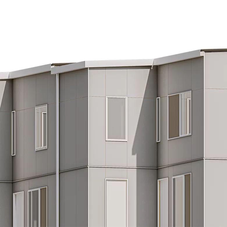
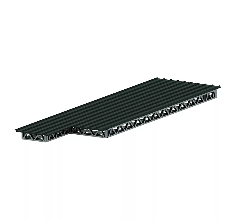
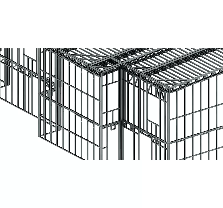
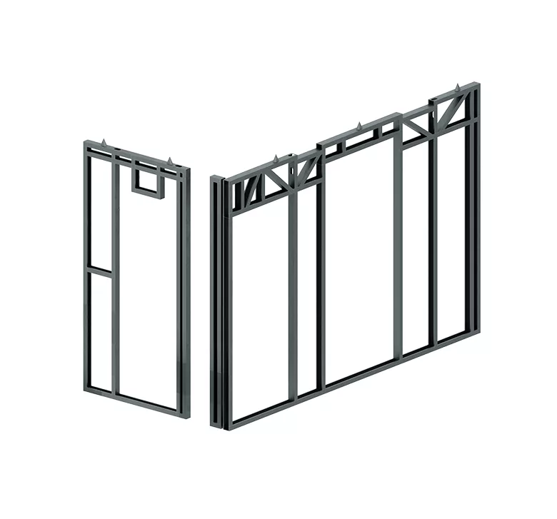
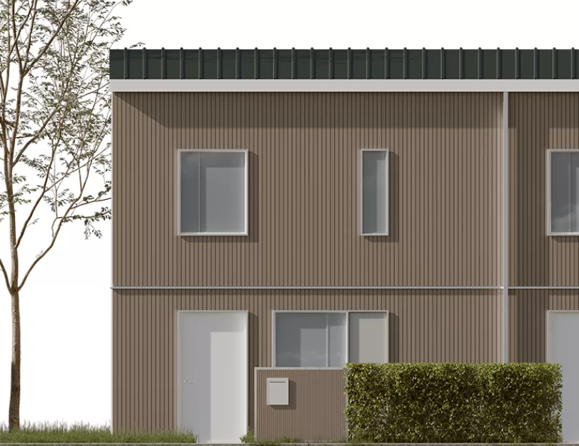
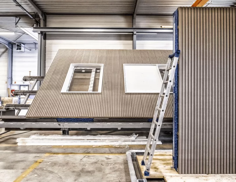
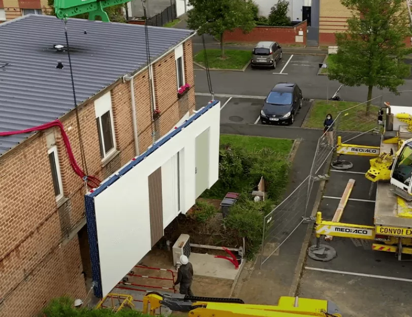
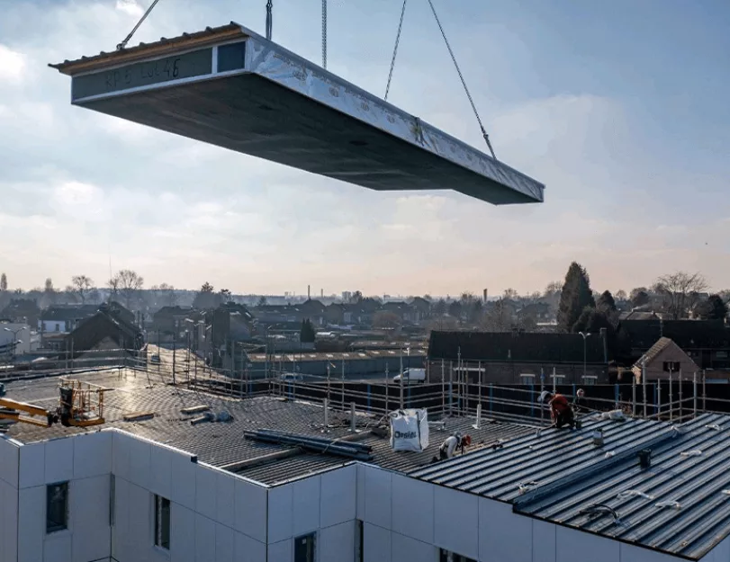
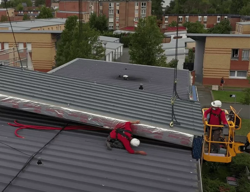
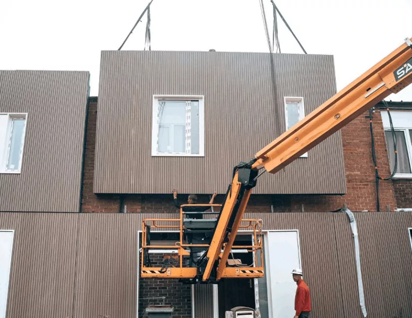
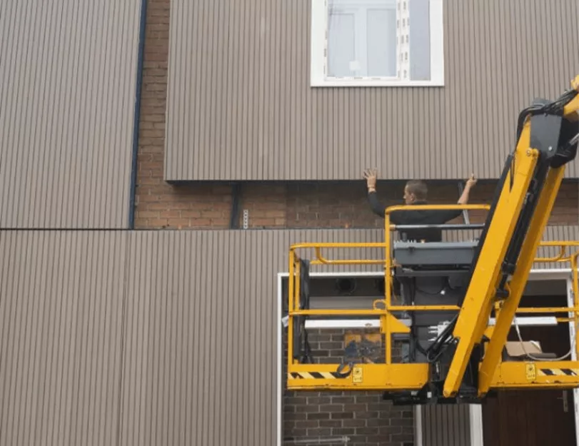
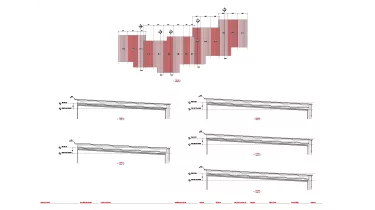
Since the buildings were already occupied, the work had to be performed quickly and with minimum inconvenience for residents. To do so, the client decided to cover existing buildings with new prefabricated exterior walls and roof panels.

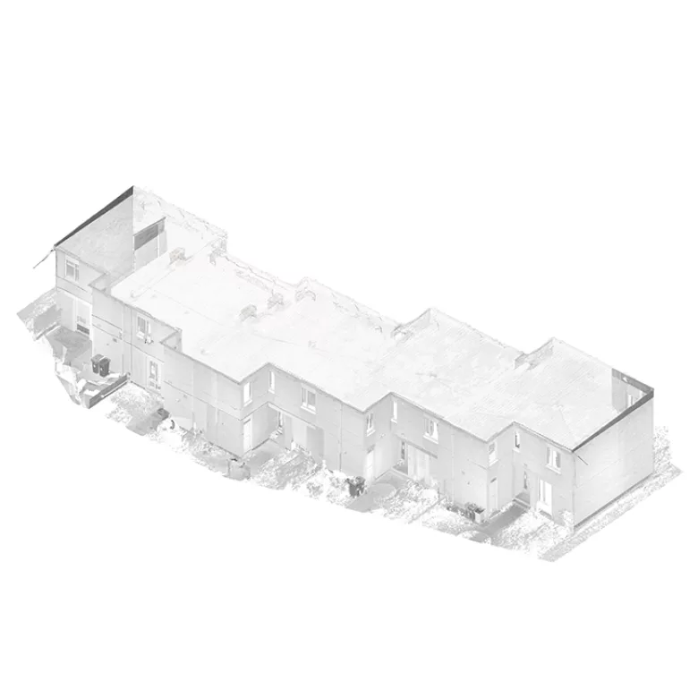
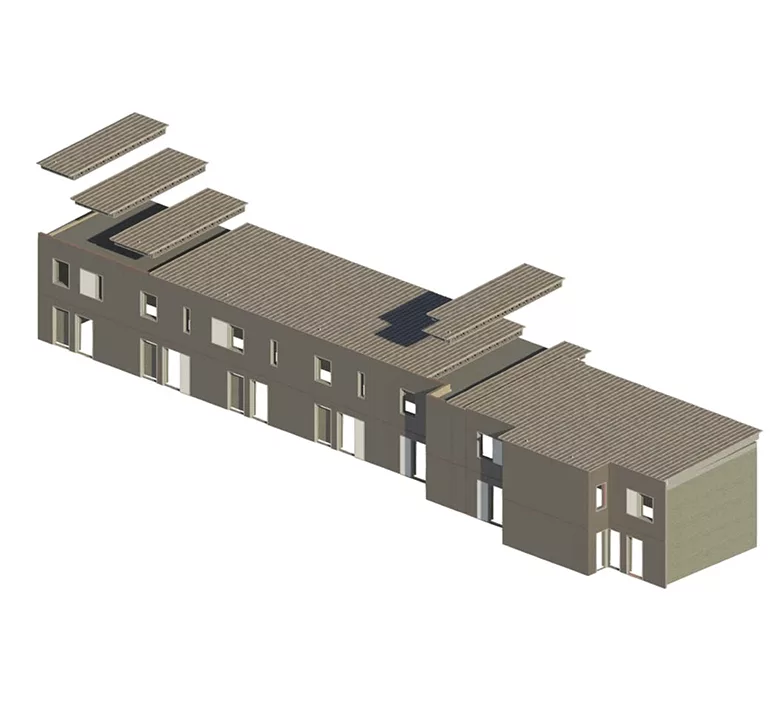
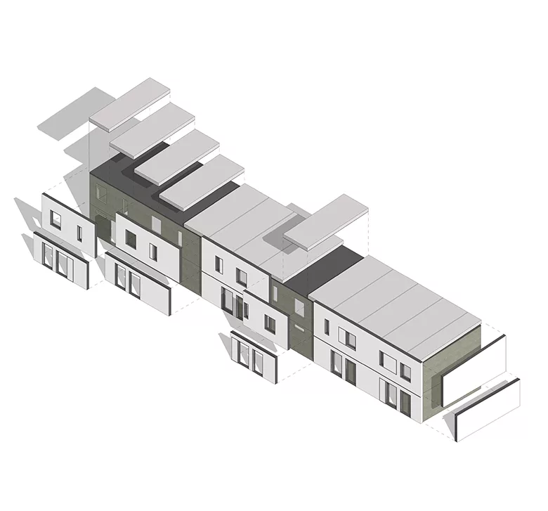
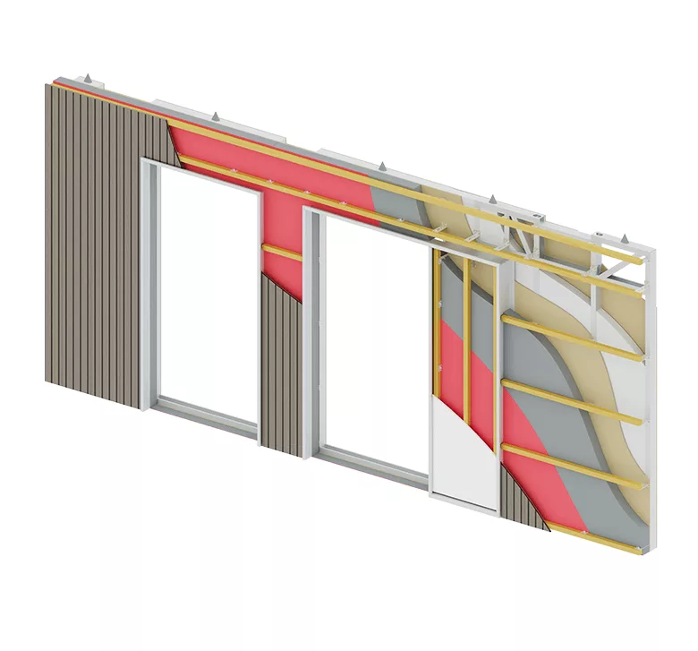
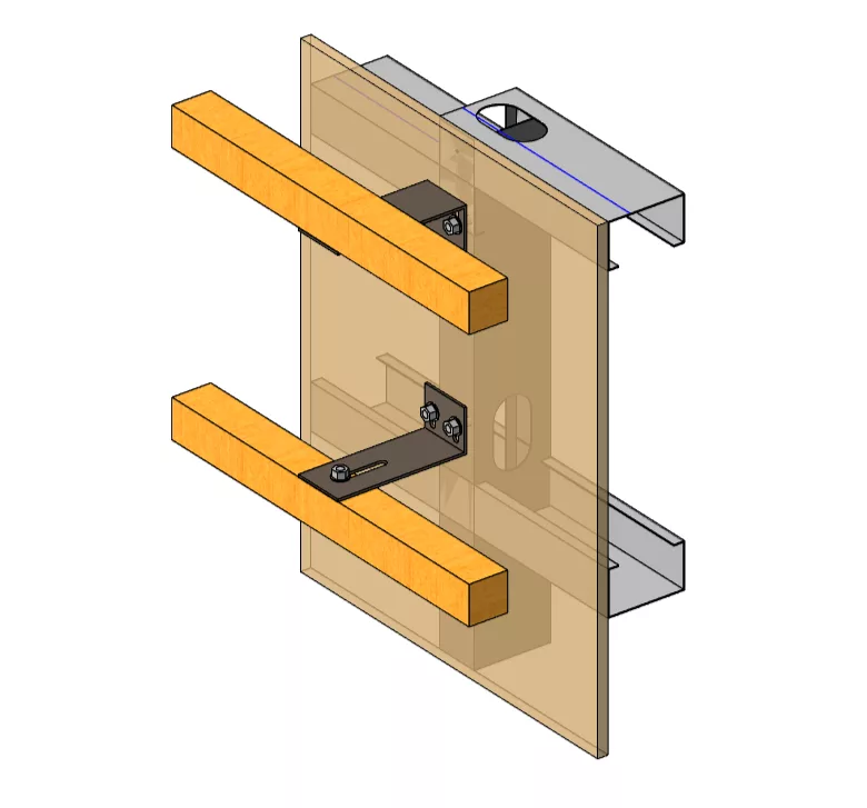
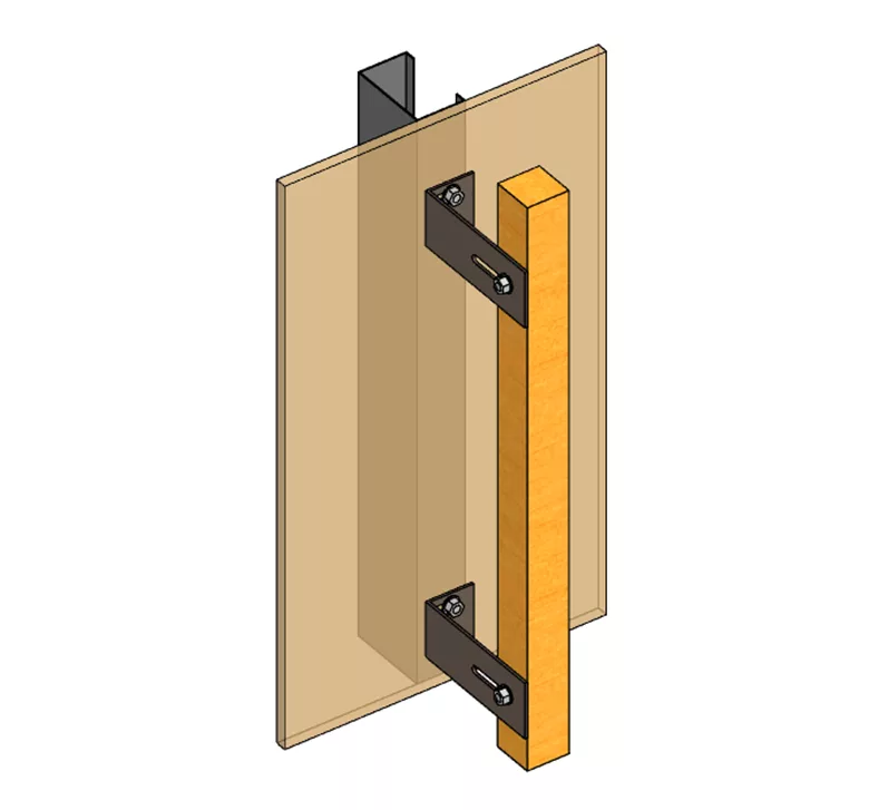
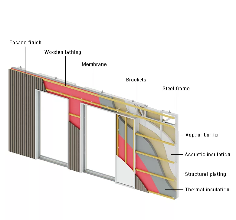
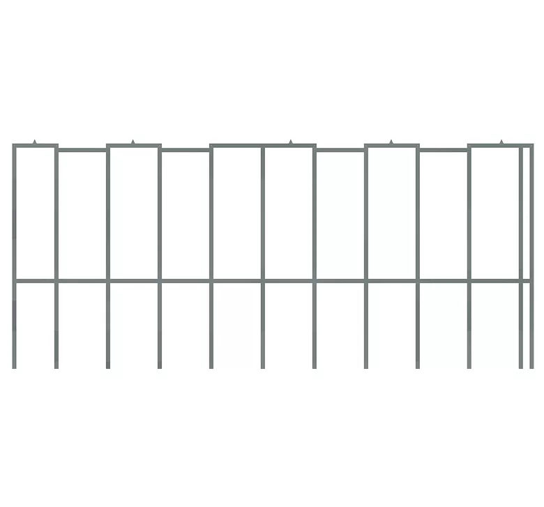
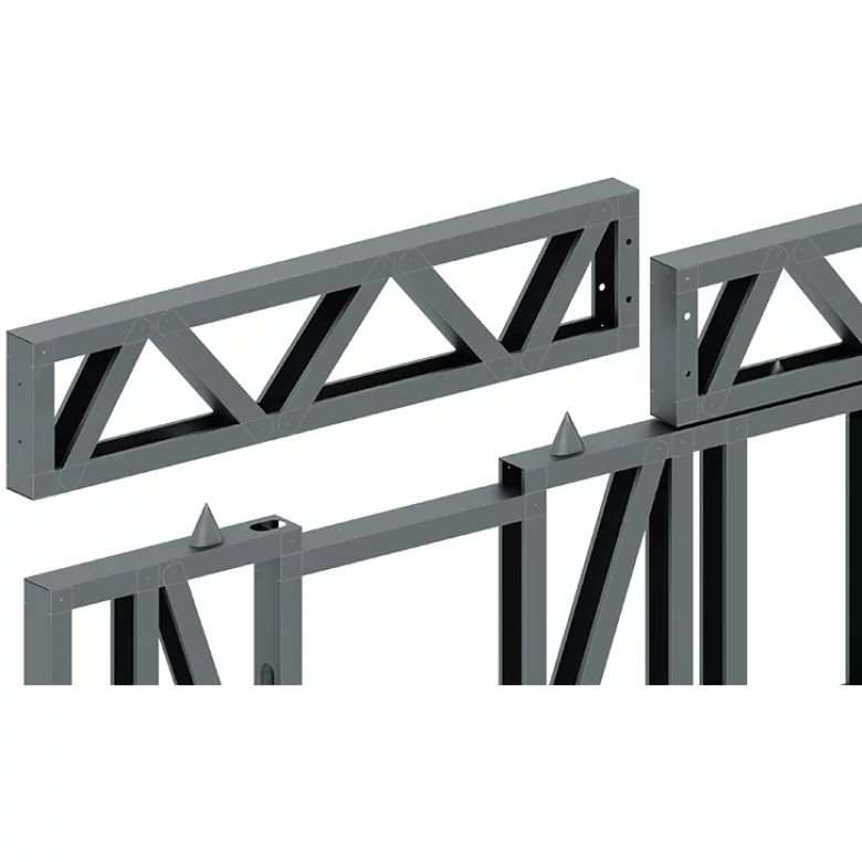
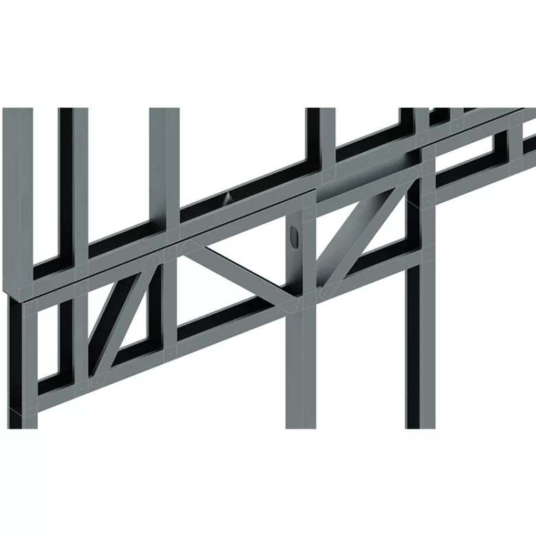
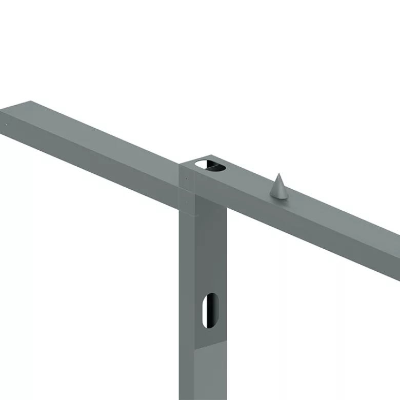
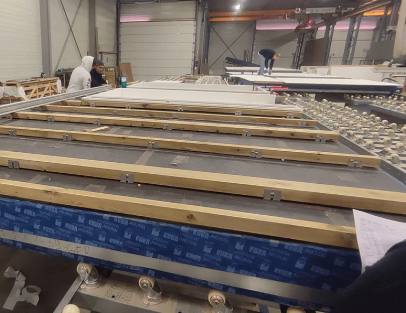
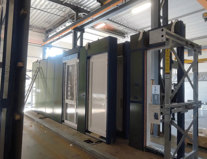
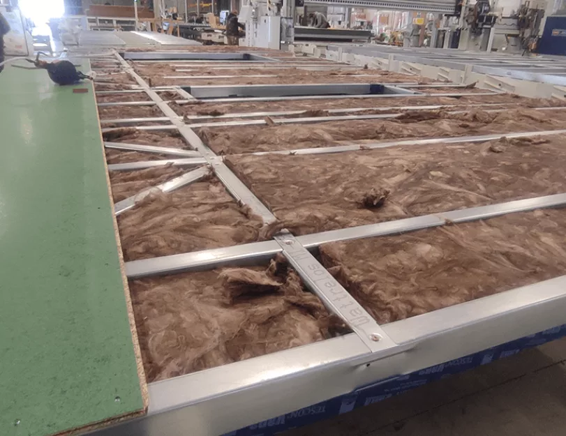
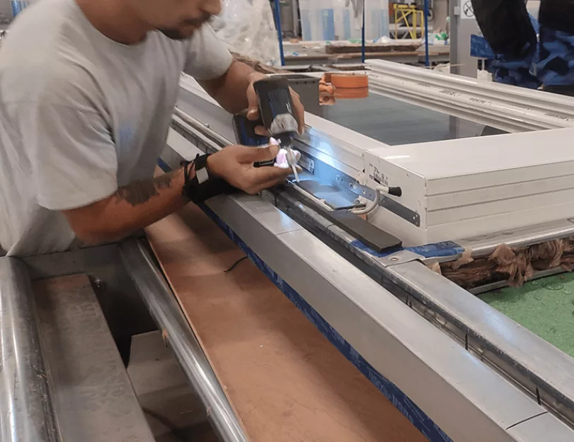
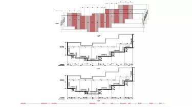
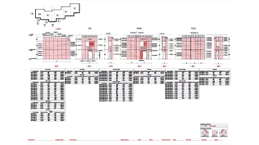
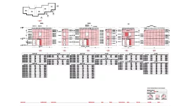
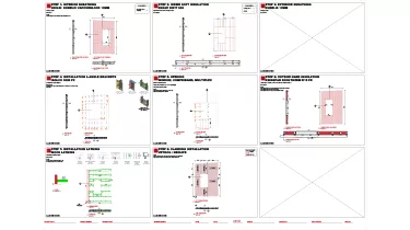
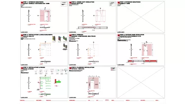
These panels consist of light gauge steel structural framing, insulation, vapor and weather barrier, and exterior finish, which makes them 100% ready for installation.

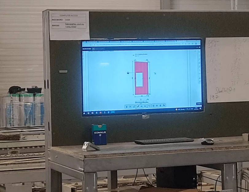
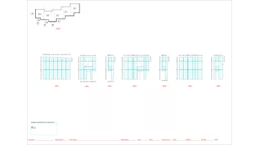
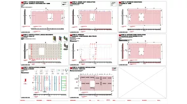
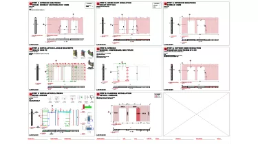
Our task was to develop a LOD 400 BIM model of those panels and create shop drawings for fabrication. LOD 400 is usually used at the construction stage. It precisely defines the quantities, size, shape, location, and orientation of elements, their relations, and their connections with each other. It also contains exhaustive fabrication, assembly, and detailing data. All the LOD 400 data should be referred to as precise and complete.

Services: BIM
Subservices: Scan to BIM, As-built drawings, Construction drawings
Industry: Residential
Object type: Multi-family home
Area: 2500 m² / 26910 ft²
Tools used: Autodesk Revit, Agacad Metal Framing, Autodesk ReCap, Autodesk AutoCAD
Share:
Project stages
1. Concept
2. Re-creation of existing situation
3. New insulated shell draft design
4. Cutting the new shell into separate roof and wall panels
5. Cladding & Roof sandwich panels design
6. Roof & Wall panels detailed design
1
1
1

Input

The following information was provided to ORIGIN to proceed with:

  • The design concept for the wall and roof structure, and its interconnections;
  • Architectural plans and details;

This project is a renovation, so it starts all from the existing building, with respect to the current dimensions of the building and the positions of doors and windows.

Step 1. As-built capture and re-creation of an existing situation

There are numerous ways of collecting data for the BIM database to create an accurate digital representation of a building. However, some ways are more effective than others.
Traditionally, surveyors would collect the information manually which is costly, time-consuming, and involves human errors. Instead of working with 2D building surveying plans, we prefer using modern technologies.

Scan-to-BIM modeling is the most accurate and efficient way to develop an as-built BIM model from the existing building. Since the point cloud captures as-built accurate data, it helps in decision-making and collision checks with upcoming elements.

At the very beginning, we had at our disposal 2 separate point clouds for each house: the point cloud of the main volume of the building (front and side facades); and the point cloud of the roof of the building.

The primary task was to merge these point clouds in order to obtain a general perspective on each of the existing buildings.


  • Stitching point clouds using Autodesk ReCap software;
  • Determine exact dimensions of existing building;
  • Define positions of existing roof, walls and openings;
  • Transfer point cloud data into Autodesk Revit software;
  • Recreate existing building using Autodesk Revit;

RESULT: 3d model of the existing building that reflects its general geometry.

1
1
1
1
1
1

Step 2. New walls and roof creation

  • Determine positions of new walls and roof based on its type
  • Create new walls with proper offset from the existing walls
  • Create a new roof with proper offset from the existing roof
  • Define position of new doors, windows and major wall and roof penetrations
  • Insert proper Revit door / window family into the correct position
  • RESULT: 3D draft model of “new skin” of the building

Step 3. Define future wall and roof panels layout

As there are manufacturing and transportation restrictions on panel dimensions, we had to consider the maximum permitted height and length for each panel. That means some of the walls or roof parts that exceed the acceptable dimensions had to be divided into several components.
For aesthetic reasons, the junctions between such components had to be invisible. So we decided to join them behind the drain water pipes.

1
1
1
1

Step 4. Wall сladding and roof sandwich panels design

Since inter-panel joints are visible, the architectural project provided an approximate layout of the wall cladding panels. However, cladding panels have certain dimensional limitations. Our task was to model everything according to the original design, considering the max and min panel sizes, and providing the appropriate fastening.

In order to hide the joints between wall cladding panels on the outer corners of the house and between the ground-floor panel and the 1st-floor panel we’ve placed an aluminum profile there.

There are different setups for the cladding of the buildings, using the two materials. Each building has one of the two claddings as the main and uses the other material for accents.

When the whole wall cladding layer is divided into separate panels, every panel has to be identified by a unique ID code.

The last step is to define the position of fixing screw holes in the Revit model based on the rules for every type of cladding. The positions of those holes are to be defined in advance since they will be made with a CNC machine. To do it fast and precisely we use the Smart Connection AGACAD plugin which automates the insertion of those holes eliminating human mistakes.

All the roof parts should be covered with roof sandwich panels, so we needed to create a layout for the roof as well.


  • Determine external borders of cladding and division of cladding panels
  • Divide wall cladding layer to conform the architect’s design
  • Determine position of fixing of screws depends on cladding type
  • Insert screw holes into the cladding panels using AGACAD plugin
  • Create roof sandwich panels layout
  • RESULT: Plan set and Bill of Quantities
1
1
1
1
1
1

Step 5. Panels detailed design

The panel, which consists of a steel frame, structural plating, insulation, and facade cladding, arrives on the construction site fully assembled. Due to 95% prefabrication, all the installations are performed extremely fast.At this stage, the task was to develop detailed drawings for production. We knew that these panels would be manufactured on a horizontal production line. So, during the Revit detail design of the model, we built up the walls layer by layer: from the outside inwards, starting from the wall cladding towards the steel frame.

The purpose of the wooden lathing is to provide a surface to attach the wall cladding with screws. The type of wall cladding determines the orientation of the lathing structure – vertical or horizontal. There are several combinations between the wooden lathing positions and the possible positions for the steel frame profiles in the wall panel.

L-Brackets are used to attach the horizontal and vertical lathing structure to the steel frame wall structure. A bracket itself has 4 different possible orientations: up, down, left, and right. The wooden lathing has two possible positions relative to the bracket: wood on the top/bottom of a bracket, and wood on the left/right of it.

Since the process is repetitive and knowing all possible combinations of elements’ positions, we automated the insertion of wooden lathing and brackets utilizing the AGACAD plugin with pre-configured framing settings.

Wall panel elements:

  1. Wall cladding;
  2. Wooden lathing;
  3. Brackets;
  4. Structural plating;
  5. Steel frame;
  6. Thermal and sound insulation.
1
1
1
1

Steel frame

The main bearing part of the panel is a light steel frame. It is produced using light gauge steel roll-formers machines according to strict standards and is assembled off-site. So the design needs to be perfectly accurate to avoid mismatches.

Since the facades of the houses are partially ledged, the connection between the sidewalls and the front walls might be specific.

In order to avoid engineering mistakes, simplify, and automate the process of steel frame creation for each house, we also prepared certain configurations using the AGACAD plugin. Each depends on the position of the openings, the shape of the wall element, etc.


  • Define outer edge steel profiles position
  • Define position of Jack studs next to windows and doors
  • Define position of horizontal bracing
  • Define position of anchor rivets
  • Define position of recesses
  • Define position of cones
  • Define position of lifting slings
  • RESULT: AGACAD wall framing configuration

To connect the wall panels with the existing building and each other, there are several connectors included in the steel framing. For example:

Cones

Сones are custom-made connector pieces that are built-in on the top track of wall panels. The panel that is placed on the top, has an opening in its bottom track to receive this connector.

Anchor bolts and Recesses

Anchor bolts are used to connect the ground floor wall panels to the foundations.

Recesses are cutouts on the top of each wall panel, where a gibbet will be inserted to connect the new wall panel with the existing building. The recesses follow the positioning of the anchor bolts.

Lifting slings

The panels are lifted with built-in slings. The slings require two service holes in the frame. One on the top track so the lifting loop can exit the wall panel — and one on the stud, so the lifting loop can be attached. Each panel has a minimum of two lifting slings.

After the steel frame configuration had been defined we determined the behavior of other layers of the wall around the openings and adjusted the offsets for the structural plating, sound, and thermal insulation.

1
1
1
Production

The last step is the production itself, transportation to the construction site, and installation. Production was carried out by the customer’s side on the basis of workshop drawings produced by the ORIGIN team.

Benefits
As it is pre-assembled frames the contractor or construction company retains maximum freedom on the construction site
High accuracy of manufactured structures
An extremely fast renovation using qualitative “off-site” solutions
Easy installation process
On-site works took very short and caused minimal inconvenience for residents
Tools used
1
Autodesk Revit
1
Agacad Metal Framing
1
Autodesk ReCap
1
Autodesk AutoCAD
view project view more view photos