Search...
Overview

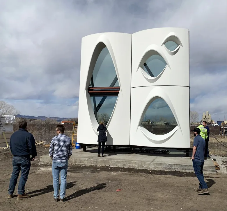
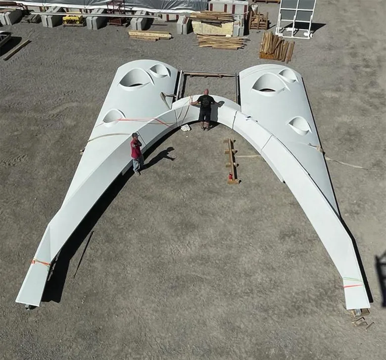
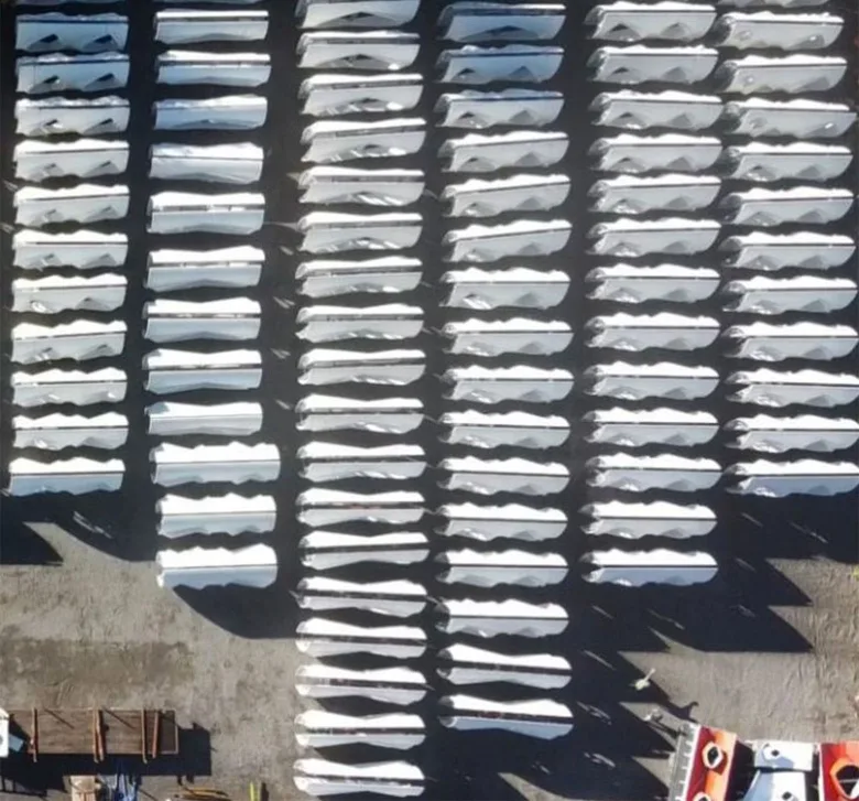
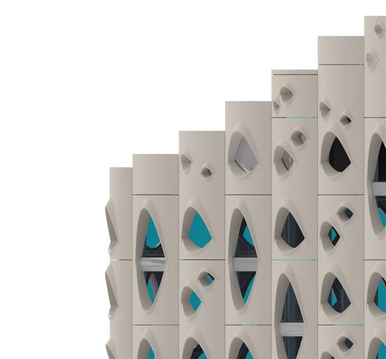
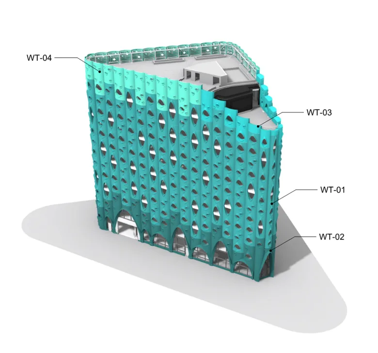
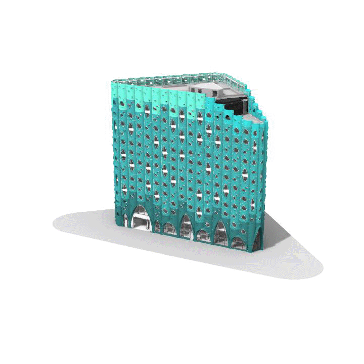
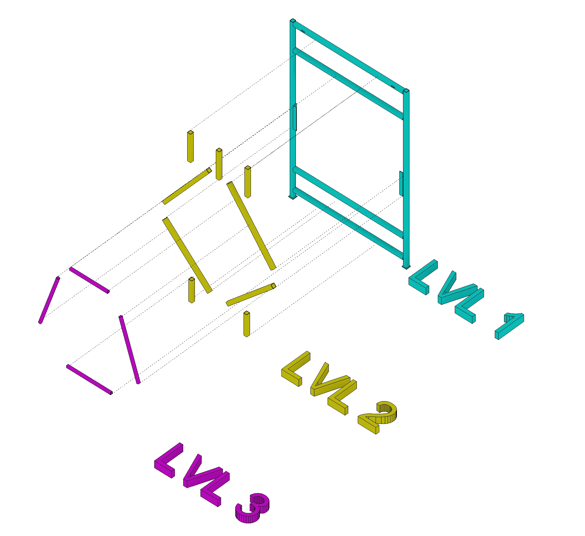
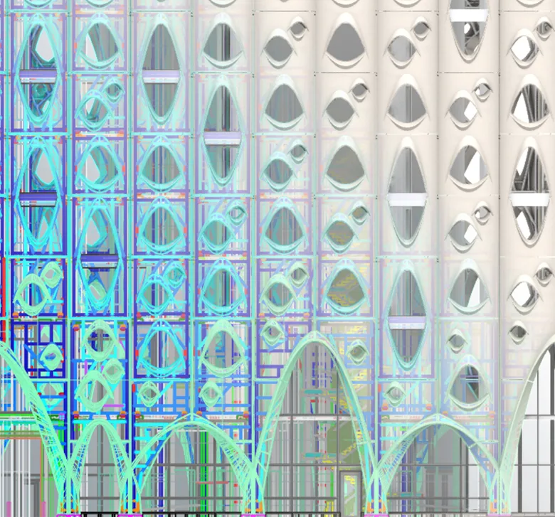
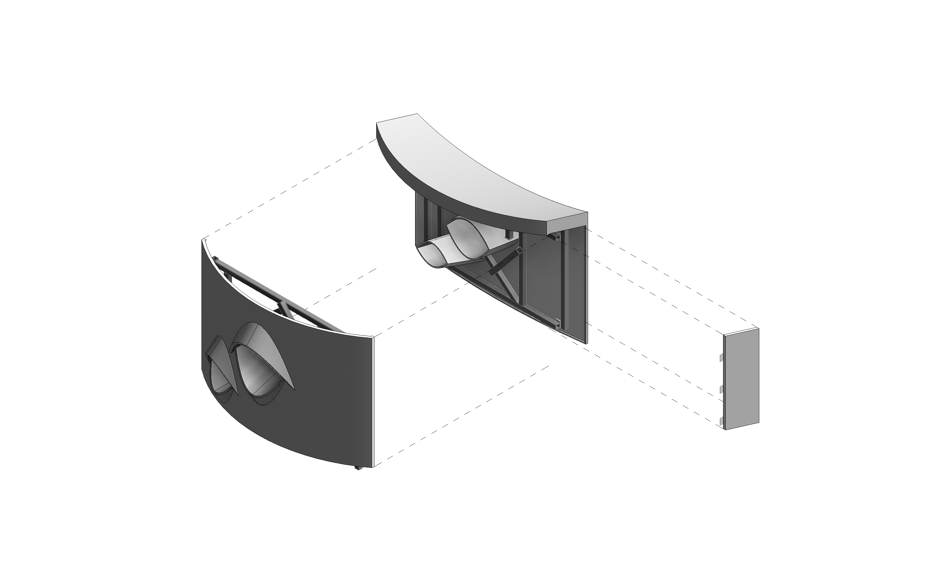
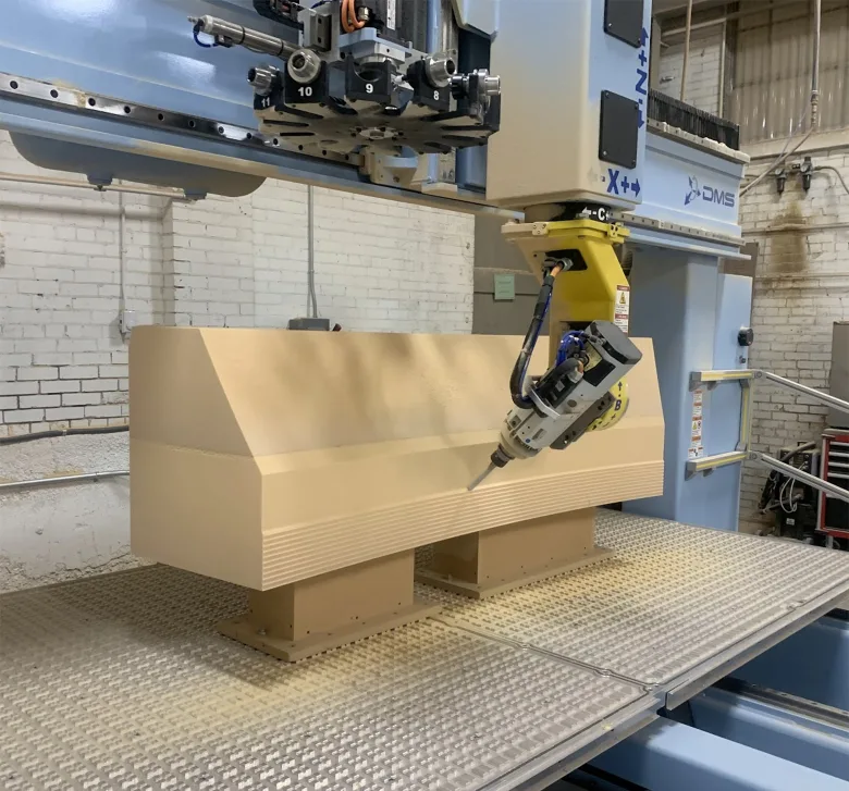
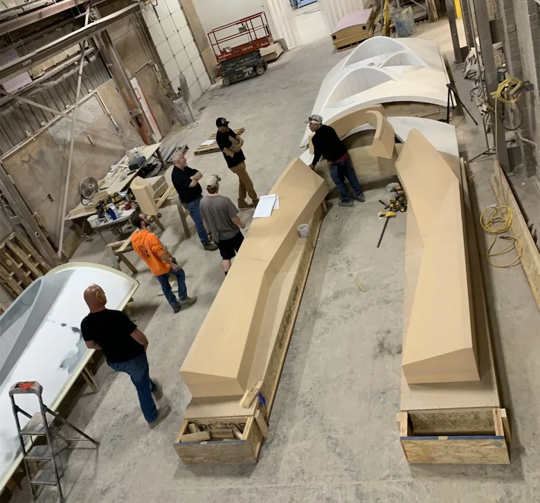
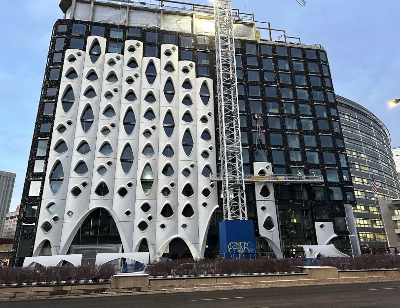
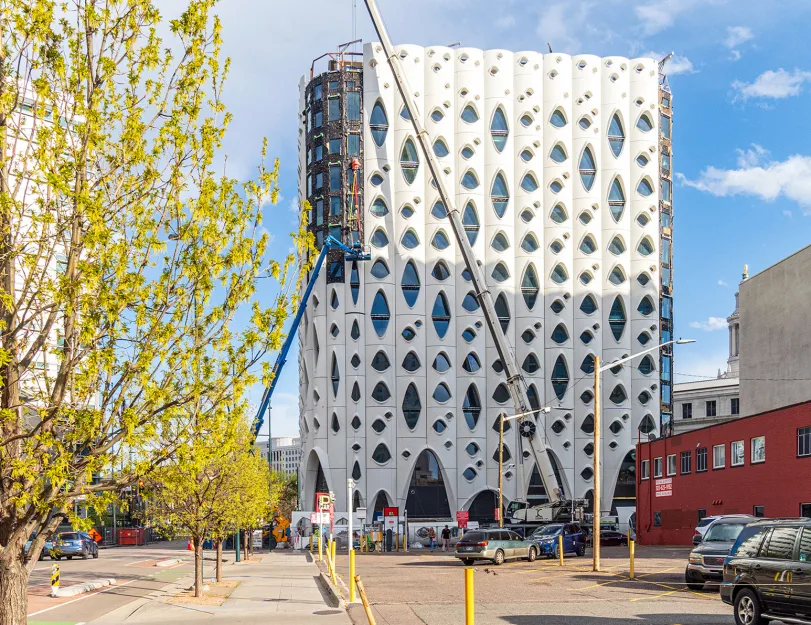
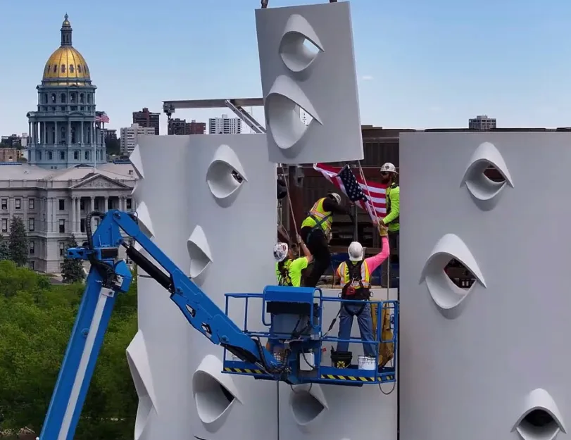
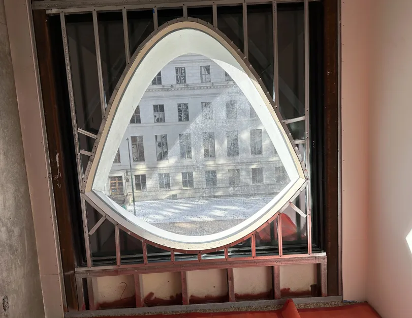
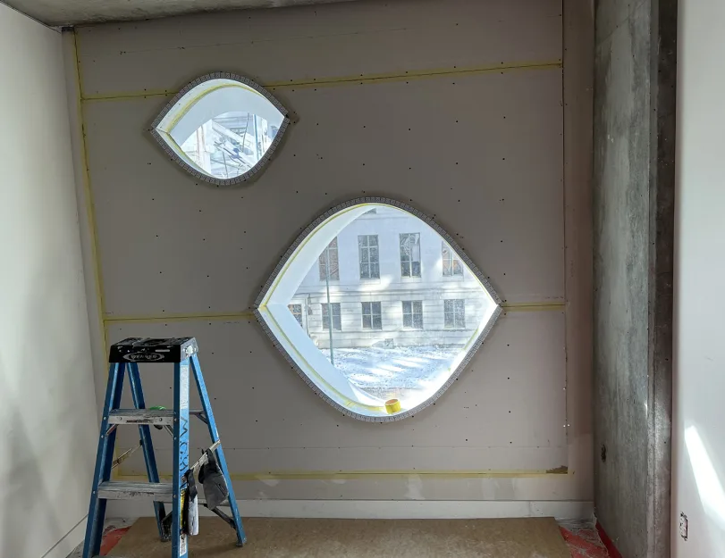
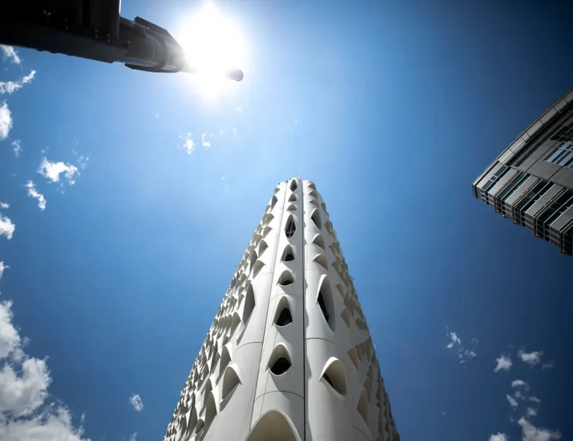
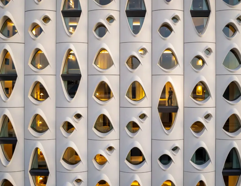
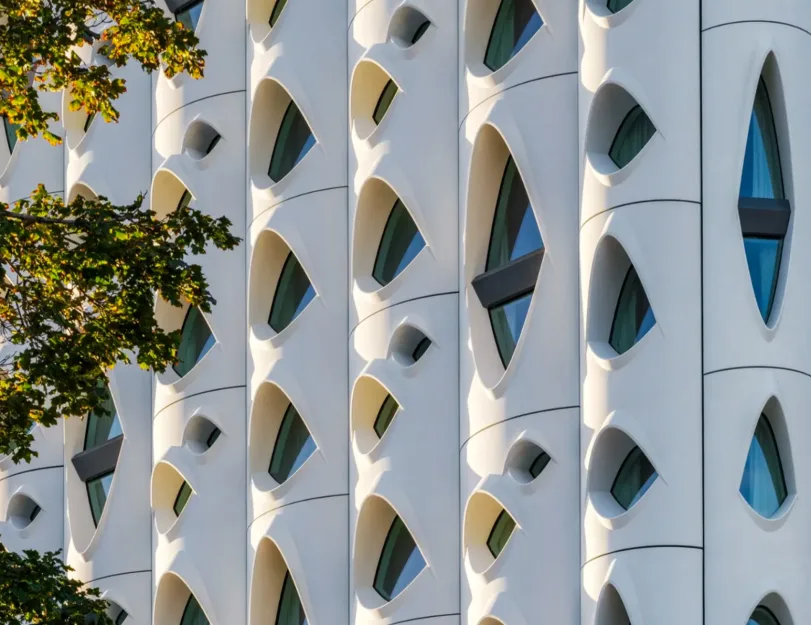
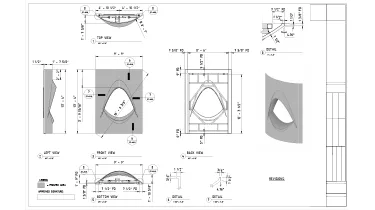
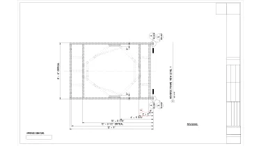
ORIGIN contributed to the development of the Populus Hotel in downtown Denver, Colorado — an award-winning landmark designed by Studio Gang. Our client was hired to manufacture the exterior GFRC panels, the defining feature of the building’s biophilic design.

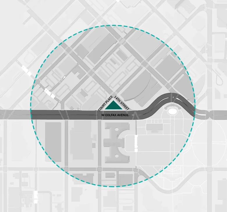
The building follows the triangular shape of the site, which is bound by 14th Street, Court Place, and Colfax Avenue. Once home to one of Colorado’s earliest gas stations, this is a special location where the civic, business, and cultural districts of Denver intersect.

Category: ARCHITECTURE, STRUCTURE, BIM
Services:GFRC/UHPC & architectural precast engineering, Hot-rolled steel design and detailing, Fabrication/Installation drawings, PDF/CAD to BIM conversion, Production tickets
Industry:Commercial
Object type:Hotels
Area:7534 m² / 81100 ft²
Tools used:Rhinoceros 3D, Autodesk Revit, Autodesk Advance Steel, ARKANCE (formerly AGACAD) Smart Documentation, Dynamo, Advance Steel Extension for Revit, Rhino.Inside.Revit
Share:
Project stages
1. Analysis of the facade structure
2. Model coordination
3. Design and modeling of frames and fastenings
4. Development of drawings and detailing
5. Development of Dynamo scripts
6. Panel design in Rhino
1
1
1
1

Interesting facts

  • Populus is the first “carbon positive” hotel in the United States, meaning it’s committed to reducing emissions from construction and operations over time.
  • The hotel operates a “One Night, One Tree” program in partnership with the National Forest Foundation — planting a tree in Colorado’s forests for every night a guest stays.
  • In total, the hotel’s facade is divided into four sections and features 88 types of scallop-shaped panels and approximately 60 types of base panels, totaling 374 panels.
  • The biggest panels reach 32’-10” height, have 376.77sqft area, and weigh over 5873.02 lb.
  • The project requires a high level of digitalization, increasing the quantity of manufacturing drawings — eventually, the biggest set of drawings for 1 panel contains 85 pages.

Inputs & project deliverables

Inputs:

  • Architectural and structural drawings;
  • Coordinated Rhino model;
  • Additional design intent sketches from the client and structural team.


Project deliverables:

  • Refined design of panels;
  • Steel frame design;
  • Precise drawings for manufacturing;
  • Detailed drawings for steel pieces;
  • CNC files;
  • Bill of materials.
1
1

Notable aspects of the building’s design

The building is instantly recognizable for its exterior design, which is textured with curved body panels and unusual eye-shaped windows. This design was inspired by the knotted white bark of Aspen trees, which has been a symbol of Colorado for decades. This also defined the original name of the architectural project, as the Latin name for aspen trees is Populus Tremuloides. The panels are acid-washed to expose the aggregate, resulting in a light, natural coloration.

The windows vary in size and shape according to interior use. Large arched portal openings at street level welcome visitors to public spaces, while smaller ones highlight the privacy of the guest rooms.

The windows’ outward-projecting “lids” are shaped and oriented in response to the sun, helping limit solar heat gain by shading the interior. To achieve this complex, solar-responsive design, GFRC was the ideal material choice. It is an environmentally responsible material that supports the building’s sustainability goals.

Facade structure

The overall facade of the building isdivided into zones based on the type of facade panels:

WT-01: Typical tower cladding

The major facade area features a scalloped GFRC rainscreen cladding system with an articulated brow. Panels span two floors and are arranged in a staggered joint pattern.

WT-02: Tower base cladding

GFRC cladding at the base of the curtain wall follows the vertical divisions of WT-01 and includes 30-feet-high panels, small benches, and spandrels all around the building.

WT-03: Tower top cladding

A two-sided GFRC parapet with shoe-mounted glass railings is located on the rooftop terrace.

WT-04: Tower top screen wall

Similar to the WT-01, a single-sided GFRC screen wall with unglazed openings is located at the mechanical roof.

1
Facade zoning

Coordination between models

Our journey began with an in-depth investigation of various tools that could provide an optimal data exchange process, shorten turnaround time, and enable efficient adjustments when needed.

The initial design concept was created in Rhino, where all coordination also took place. However, after considering several options and our team’s broad skill set, we decided to continue development partially in Revit and Advance Steel. Since they offer numerous useful settings and capabilities, we were able to output the resulting drawings in a format most convenient for our customer.


Our work plan involved:

  1. Finalizing the GFRC geometry in Rhino;
  2. Importing the geometry into Revit along with the 3D frame sketches;
  3. Designing frames and connections in Revit using the imported sketches;
  4. Creating the set of drawings in Revit;
  5. Importing finalized steel geometry into Advance Steel and adjusting it for steel detailing;
  6. Creating steel detailing drawings in Advance Steel;
  7. Importing the finalized assemblies (GFRC + frames) back into Rhino for further coordination.


To transfer geometry between Rhino and Revit, we used two options:

  • Exporting geometry with the help of the built-in tools and importing it into the Revit family;
  • Importing directly via Rhino.Inside.Revit, which turned out to be the quickest and most efficient way to transfer geometry without quality loss.
Breaking the frame into levels

Frame design approach

As a typical solution, frames have been designed using mostly steel angles and hollow structural section tubes (HSS) of rectangular and square profiles, developed for further hot-dip galvanization. The curved shape and variable depth of the GFRC scallops led to the need for more complex frame configurations, including:

  • Adding extra steel supports for larger window returns, which are pretty deep due to the intricate panel geometry;
  • Inserting additional steel members to accommodate the proper configuration of a flexible attachment mechanism;
  • Developing a “level organization” of the steel frame representing the frame assembly sequence. For example, the first layer forms a rigid base frame in a single plane, while subsequent layers overlap it sequentially;
  • Modifying the flexible attachment mechanism to provide efficient support for the curved panel geometry.
1

Individual frame element detailing

All frames were galvanized to enhance corrosion resistance, which required a vent-hole system. This not only made each steel component unique but, in some cases, directly influenced the layout of adjacent frame elements. Therefore, to ensure clarity and precision, our team proposed a dedicated set of single-part drawings for each frame.

Leveraging our team’s expertise in engineering software, we used Advance Steel with the Revit extension as the most optimal solution for this task. Thanks to the solution’s seamless model export, advanced steel detailing tools, and automated drawing generation, we were able to significantly streamline the documentation process.

Frames eventually evolved into larger, more complicated structures with interconnected elements.

Working with fastenings and connections

Another significant feature of this project was the variety of unique fastenings and connections. These fall into two main groups:

  1. Panel-to-panel connections. They are primarily represented by a pin system: as the pin passes through an opening in the upper frame plate, panels get stacked vertically. In addition, some panels rely on steel tubes and tracks that rest on adjacent GFRC frames for extra support.
  2. Panel-to-structure connections. These connections vary depending on whether the panel attaches to steel or concrete. They typically consist of combinations of steel tubes, plates, pins, washers, and multiple connections — with a minimum of four attachment points to the building’s structural frame.
1
1
1
Development of drawings and detailing

The number of steel elements and the complexity of the frame configurations demanded a high level of detailing. As a result, the volume of manufacturing drawings increased significantly, especially compared to our typical projects.

Eventually, the drawing set for each panel consisted of:

  • Unique sheets for each “level” of the frame (plus the same views in reverse for production team convenience);
  • Separate layout for the flexible attachment mechanism (plus the same views in reverse for production team convenience);
  • Additional reverse views for sheets and the attachment mechanism, to ensure convenience for the production team;
  • General frame layout sheets with additional sections and tags for each steel element;
  • Individual single-part drawings for every steel component (typically 30 to 60 sheets per panel);
  • Schedules and take-offs, along with schemes of typical frame assembly solutions.

In addition to the frame drawings, the GFRC scallops required dedicated sheets featuring new projections, connection details, window tags, and quantity take-offs for specific elements and panel types with variable heights.

From frame levels to manufacturing drawings

1

Development of Dynamo scripts

In addition to using various external plugins and add-ons, we developed seven custom Dynamo scripts tailored to this project. These tools significantly reduced manual work and shortened the timeline for drawing production and remodeling of Rhino-based geometry.

Key examples include:

  • A script that reads imported draft Rhino geometry of frames and places all corresponding steel elements in Revit;
  • A one-click tool for modifying the flexible attachment mechanism configuration;
  • A script that automatically generates additional HSS elements to accommodate the flexible attachment mechanism based on predefined rules;
  • Several scripts that populate all required drawing and schedule data (including steel part sorting by type and length, mark assignment, weight and area calculations, and more).

Panel design and development in Rhino

The final stages of the project focused on the two-sided GFRC parapet at the rooftop terrace, as well as smaller panels around the building base (including benches and spandrels).

As the project neared completion, input from other contractors became more limited. Using this opportunity, our team took a more active role in the initial design of panels, frames, and attachment systems.

In particular, we went the extra mile by delivering the following:

  • Suggested adjustments to the rooftop panel breakdown;
  • Provided optimal frame configurations based on our own assessment;
  • Proposed fastening design solutions for improved constructability.

As a result, we were able to significantly improve the workflow. Ultimately, our team delivered clear, easy-to-follow drawings and instructions to support both manufacturing and installation processes.

1
Double-sided GFRC parapet for the terrace

1
1

Manufacturing process

The complex geometry of the panels pushed the limits of standard fabrication. The initial design aimed to minimize the number of unique panel types and avoid pattern repetition. By shifting the panels’ orientation, it was possible to achieve distinctly different appearances from the same mold. Ultimately, 64 unique molds were manufactured, each incorporating four different scallop types and accommodating varying panel trunk-form radii.

The manufacturing team employed two different five-axis CNC machines to fabricate the molds from medium-density foam, while the scalloped elements were produced using a rib kit made from high-density foam.

Gallery
Drawings

Click on preview to view high-resolution PDF drawings

Benefits
Accuracy and consistency from design to fabrication, thanks to seamless integration of diverse software platforms
Innovative solutions (f.e., custom frame and fastening designs) meeting specific project needs and enhancing durability
Streamlined design process and reduced errors thanks to using Dynamo scripts and internal tools
Innovative insights and solutions thanks to our team’s expanded role in the final design phase
Tools used
1
Autodesk Revit
1
Autodesk Advance Steel
1
Advance Steel Extension for Revit
1
Rhinoceros 3D
1
Rhino.Inside.Revit
1
Dynamo
1
ARKANCE (formerly AGACAD) Smart Documentation
view project view more view photos