Search...
Overview

The client reached out to the ORIGIN team to bring to life the vision of GFRC panels and the fiberglass finial for the cupola. The goal of the project was to develop detailed drawings to be further utilized by our client in manufacturing.

The challenge:
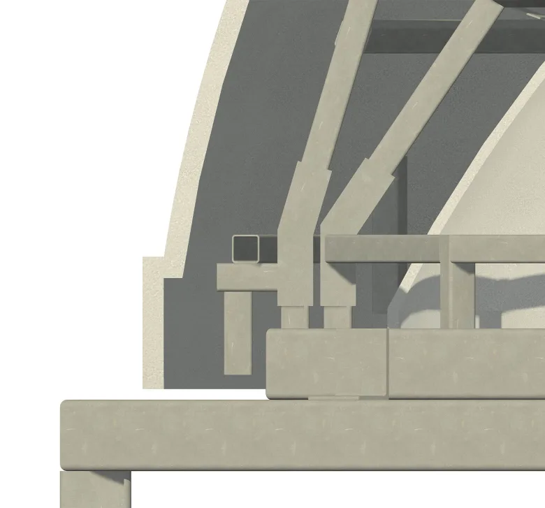
The complexity of a structure — with the suggested layout featuring two outer cupola panels, two interior panels, and a finial. A sophisticated GFRC frame was designed to support the four large panels and the finial while adhering to the constraints of the existing superstructure, which could not be modified. Additionally, the design incorporated solutions for flashing installation.

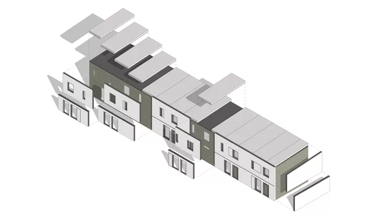
Input: Architectural drawings set, architectural model

Project deliverables:

  • Shop drawings set
  • Manufacturing drawings
  • Steel detailing drawings
Services: STRUCTURE, BIM, ARCHITECTURE
Subservices: Hot-rolled steel design and detailing, GFRC facade panels design, Fabrication/Installation drawings, Construction drawings
Industry: Commercial
Object type: Hotels
Area: 66 m² / 720 ft²
Tools used: Autodesk Advance Steel, Autodesk Revit, ARKANCE (AGACAD) Smart Documentation
Share:
Project stages
1. Analysis of the original architectural model and architectural design drawings
2. Calculation of the cupola’s outer and inner diameters based on the current superstructure layout
3. Design of the GFRC frame and development of connection details
4. Coordination with structural and electrical teams, along with the incorporation of the architect's markups and directions
5. Model completion and ensuring accurate coordination
6. Shop drawings development
7. GFRC & frame manufacturing drawings development
8. Steel detailing drawings development
1
1
1

Initial analysis coordination

The initial step focused on assessing the existing superstructure to evaluate its suitability for attaching the GFRC cupola. Upon analysis, it became clear that the current configuration lacked sufficient attachment points required to securely install the GFRC cupola.

Since modifying the superstructure was not an option, the ORIGIN team suggested the installation of additional beams — they were strategically placed to provide the necessary attachment points for the dome structure. Such enhancement ensured high stability and proper support.

Adjustment of cupola parameters

Another area identified for improvement during the analysis was the architect’s proposed outer and inner diameters for the cupola — in its original layout, it did not accommodate space for the steel frame. This made it impossible to integrate the frame into the design as initially planned.

After thorough discussions with the architect, a decision was made to slightly adjust the cupola’s dimensions. These modifications ensured a seamless installation of the steel frame while maintaining the architectural intent.

1
1
1
1
1
1
1

GFRC frame design and coordination of connection details

To create a durable and stable structure, we agreed on the following design:

  • The dome structure consists of two outer panels and two inner panels;
  • Each panel is supported by its own steel frame;
  • The inner panel frames are connected to the outer panel frames using bolted connections;
  • The outer panel frames are securely welded to the superstructure during the last step of the installation process.

With this approach, the design not only ensured durability but also facilitated precise alignment and an efficient installation process. Additionally, the limited space and stringent requirements for GFRC anchors, which were steel rods that connected the body of the GFRC panel with its frame, led to the development of a highly intricate frame design. The GFRC frame featured diagonal legs of varying lengths positioned at different angles to accommodate space limitations and adhere to the necessary anchor requirements.

As a client-focused team, we worked diligently to ensure the frame design aligned with our client’s manufacturing capabilities. Thus, every aspect of the configuration was carefully considered — as a result, making production both feasible and efficient within the given conditions.

1
1
1
1
1
1
1

Model completion

By this stage,all coordination has been completed, and all comments have been implemented. Last but not least, the finishing touch was designing the finial.

To support the finial, we designed a receiver tube to sit between the inner and outer GFRC frames. The finial itself, installed at the very end of the installation process, securely latched into the receiver tube, assuring a stable attachment.

Drawings

Click on preview to view high resolution PDF drawings

Benefits
Streamlined production thanks to a bonus scope of work (steel detailing drawings) provided proactively by the ORIGIN team
Utmost alignment of design with our client’s manufacturing capabilities
Proactive coordination with the architectural model and other subcontractors
Tools used
1
Autodesk Revit
1
ARKANCE (AGACAD) Smart Documentation
1
Autodesk Advance Steel
view project view more view photos