Advance Steel vs Tekla Structure
Outline:
Intro
Technical capabilities, ease of use, customer support, and cost are the factors that determine software quality. Therefore, while choosing the proper software for your needs, it is crucial to evaluate it according to these parameters.
Today we will compare two software products for steel structures design, detailing, and documentation development based on BIM technology.
The first one is Tekla Structures. Tekla is a software product family for analysis, design, detailing and project communication, founded in 1966, and acquired by Trimble Inc. in 2011. The company has a long history in the steel structures industry and their Tekla Structures is considered one of the oldest steel structures design and detailing software. Therefore, this product has a vast user base and much more market recognition than Advance Steel.
Advance Steel (further AS) is a software with resembling functionality, originally developed by GRAITEC. In 2015-2016 it was acquired by Autodesk, which is putting a lot of effort into updating and developing the product. One of the main advantages is its high compatibility with Autodesk’s Revit, which simplifies cross-platform work. Also, the interface of the program is built on the basis of AutoCAD, which makes it much easier for beginner users to work with, due to the familiar set of tools and cognate principles of functioning. Nonetheless, AS is still struggling for market share and acceptance.
Both products solve similar problems and offer quite alike functionality, including the possibility to create unique tools for your particular needs through programming. In this article, we will dive in and try to compare the basic and most commonly used functions of these programs.
Graphics
Interface
AS:
The interface of AS is designed on the basis of the old but gold AutoCad, considered to be the best CAD software and AEC industry standard. This makes learning AS significantly easier since users have access to many familiar functions and similar interface. However, many users believe that such an interface looks bulky, as the huge number of tools on the panels confuses the user.

Tekla:
In its turn, Tekla has a much more concise menu ribbon that can be scrolled with the mouse
wheel. Unused tabs can be easily hidden to avoid distractions. Despite its relatively modest set of tools, Tekla provides ability to perform the same operations as Advance Steel. However, according to multiple reviews, Tekla’s elaborate interface may become quite a challenge for a new user.

Visual styles
AS:
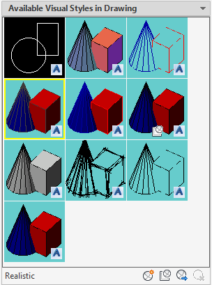
Advance Steel has a large number of customizable standard visual styles and allows users to create their own unique styles.
Tekla:
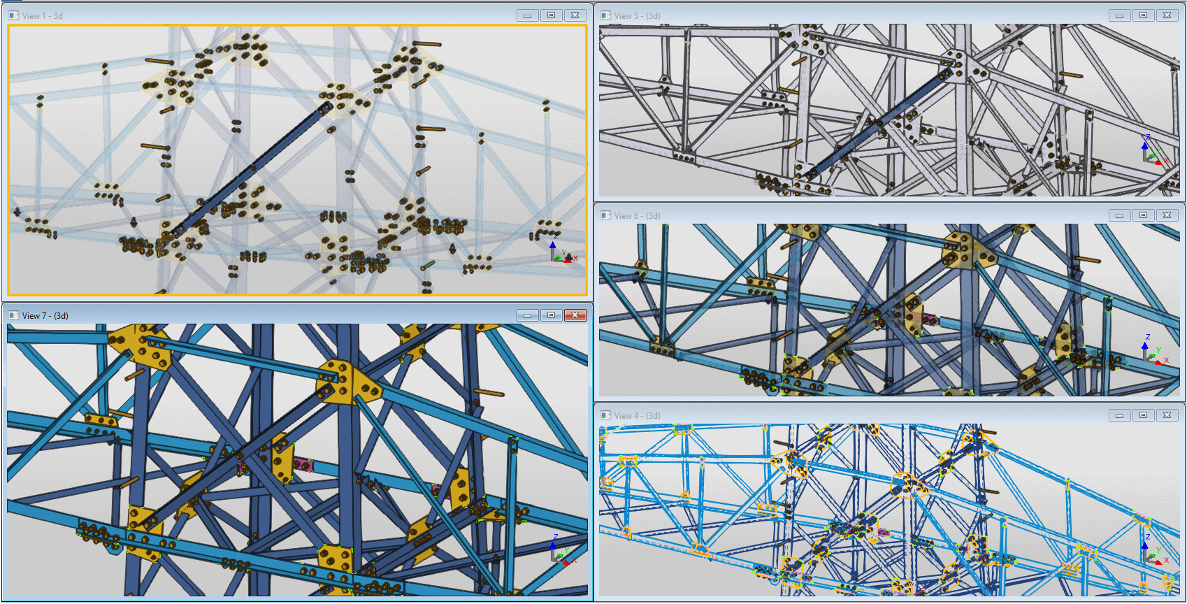
In Tekla, there are 5 standard modes for displaying parts and 5 more for displaying components in the model.
Objects display type
AS:
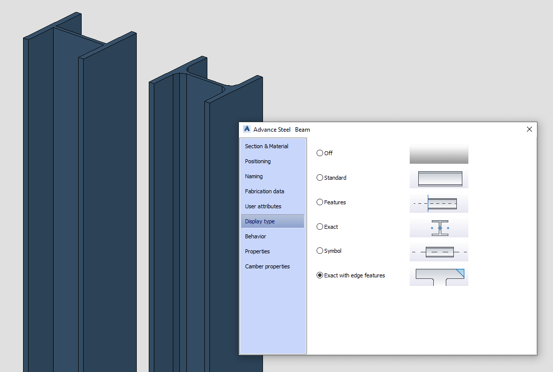
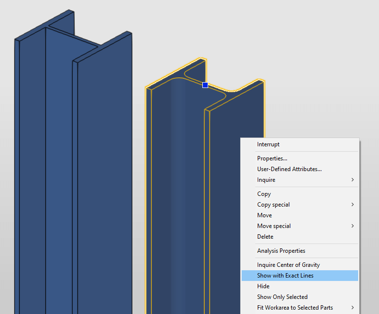
The ability of Advance Steel to switch the object’s display type to realistic (with rounded edges) on a permanent basis comes in handy. Also stands in good stead snapping to the start and end points of the profile or plate rounding function.
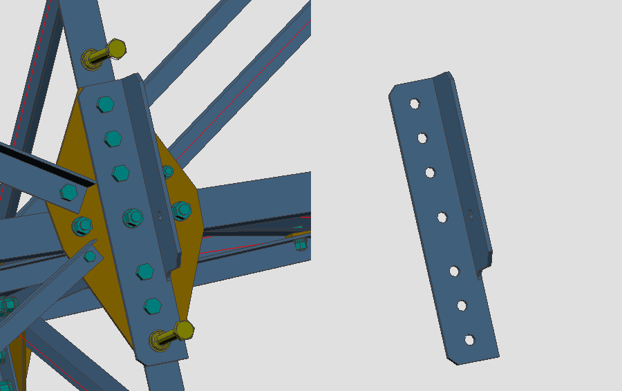
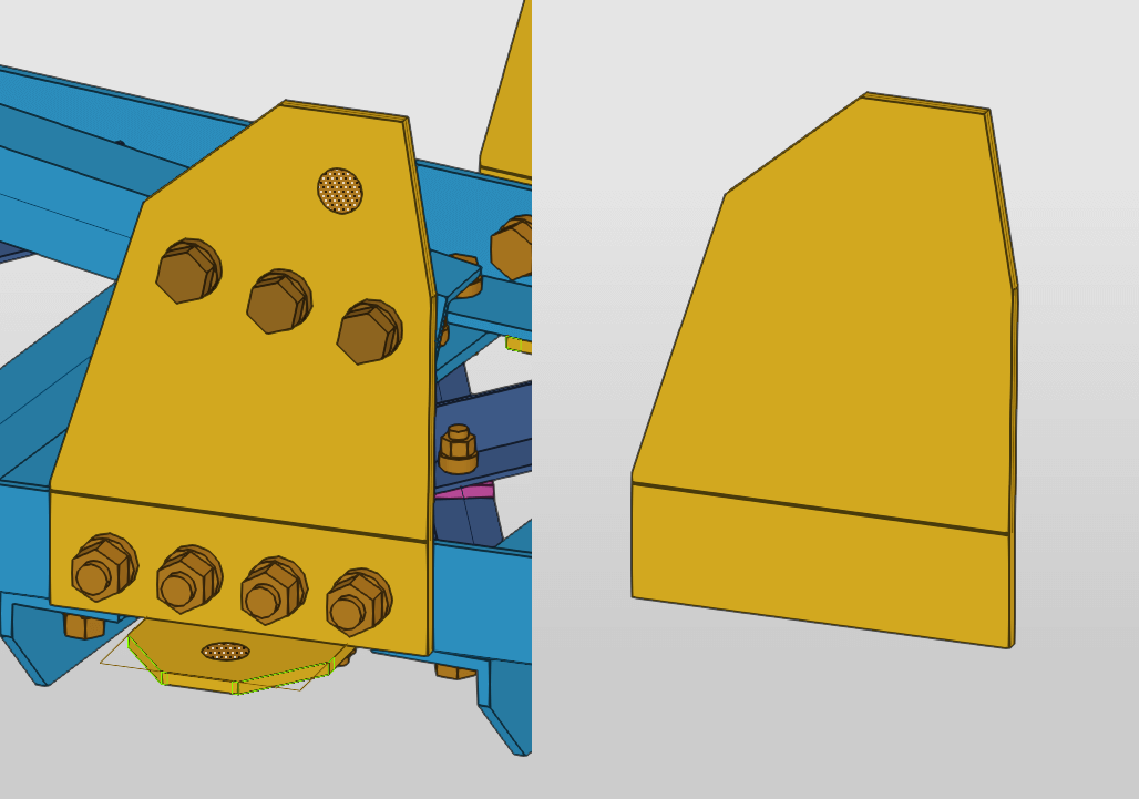
When isolating an element (except bolts), AS keeps displaying all the openings on the isolated object. When hiding the bolt itself, the opening also remains and does not disappear. As far as the bolts themselves may be mistakenly not attached to the element, this feature helps to visually assess whether the bolt cuts through the desired element. In addition, the openings are displayed as a hollow transparent cylinder, which looks more realistic.
Tekla:
Tekla also allows switching objects display type to realistic, but only temporarily until the model view is updated.
When isolating an element (except bolts), it does not display openings on the isolated object, unlike AS. It happens because the openings are set by bolts. The opening is displayed as a non-hollow, opaque cylinder, which sometimes obstructs visual perception.
Modeling
Navigation
AS:
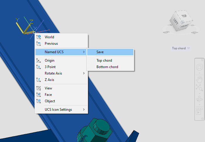
Switching between views is carried out in the same space of the 3D model with the help of a view cube, familiar to Autodesk users. It is also possible to save custom coordinate systems to generate the required non-standard views. To disable snaps in all planes except the selected one, the 2D snapping mode should be activated.
Tekla:
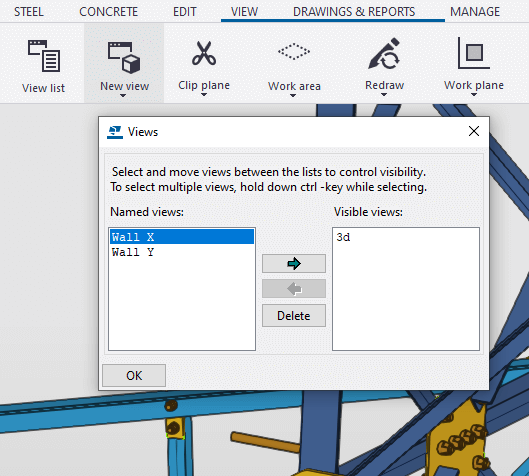
Switching between views is executed in different windows through the list of views. Required non-standard views can also be saved. When switching to another view, all snaps will be automatically carried out only in the plane of this view.
Workspace
AS:
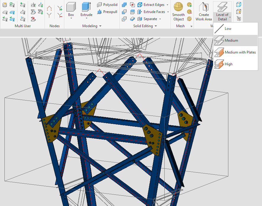
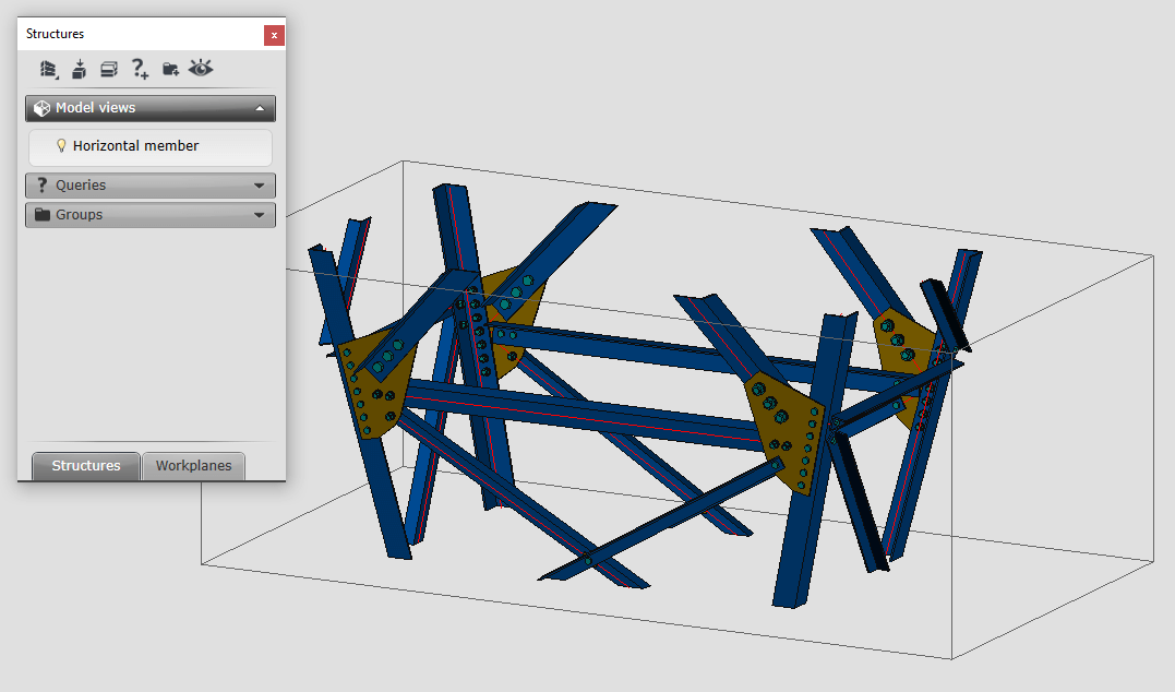
The workspace is specified as a parallelepiped. Its faces can be moved to limit the work area of the model. Objects outside this area exist but are temporarily hidden or displayed in a simplified way. The faces of this parallelepiped are strictly perpendicular to each other. You can also set the workspace with the “model view” tool. It makes it possible to set view direction by default and save customized model views for future use. Such tools greatly simplify the work with three-dimensional models.
Tekla:
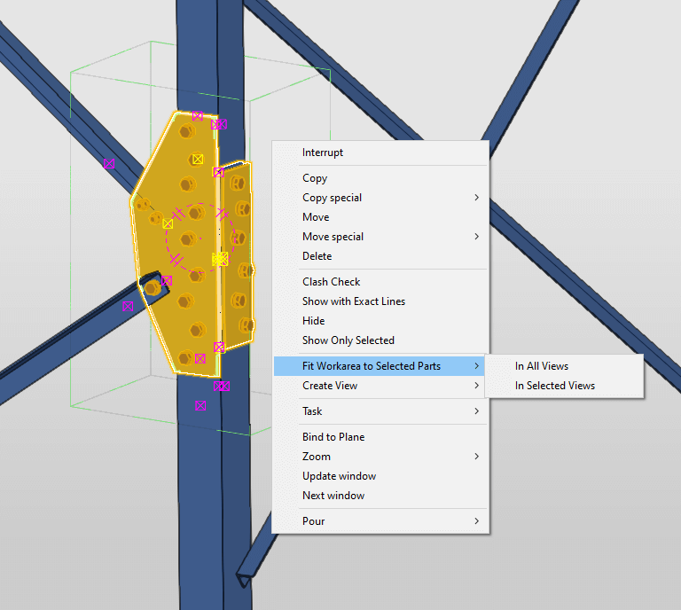
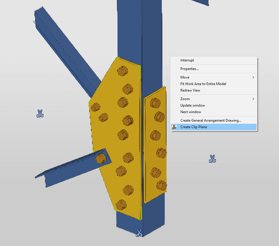
The workspace in Tekla is defined by a similar “work area” tool. However, manual adjustment of the work area faces position is not available. Instead, you can shrink and expand the work area by fitting it to the selected elements. Tekla also has an equally useful “clip plane” tool. With its help, the work area can be defined by cutting planes. These planes can be oriented in space at any angle, which gives more control over the work area. Unlike AS, Tekla’s customized workspaces can’t be saved.
Filters
AS:
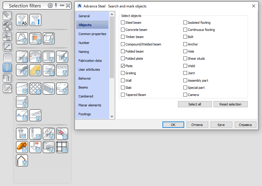
Among others, AS offers an intuitive search query generation scheme, as well as a set of standard pre-configured filters. With its help, you will be able to create queries of any complexity.
Tekla:
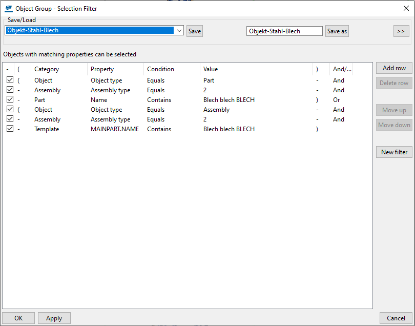
Tekla delivers much more sophisticated and detailed filter settings, which is an advantage on the one hand. On the other, it may complicate the task, due to the need to know a large number of possible attributes for each object type.
Object selection
AS:
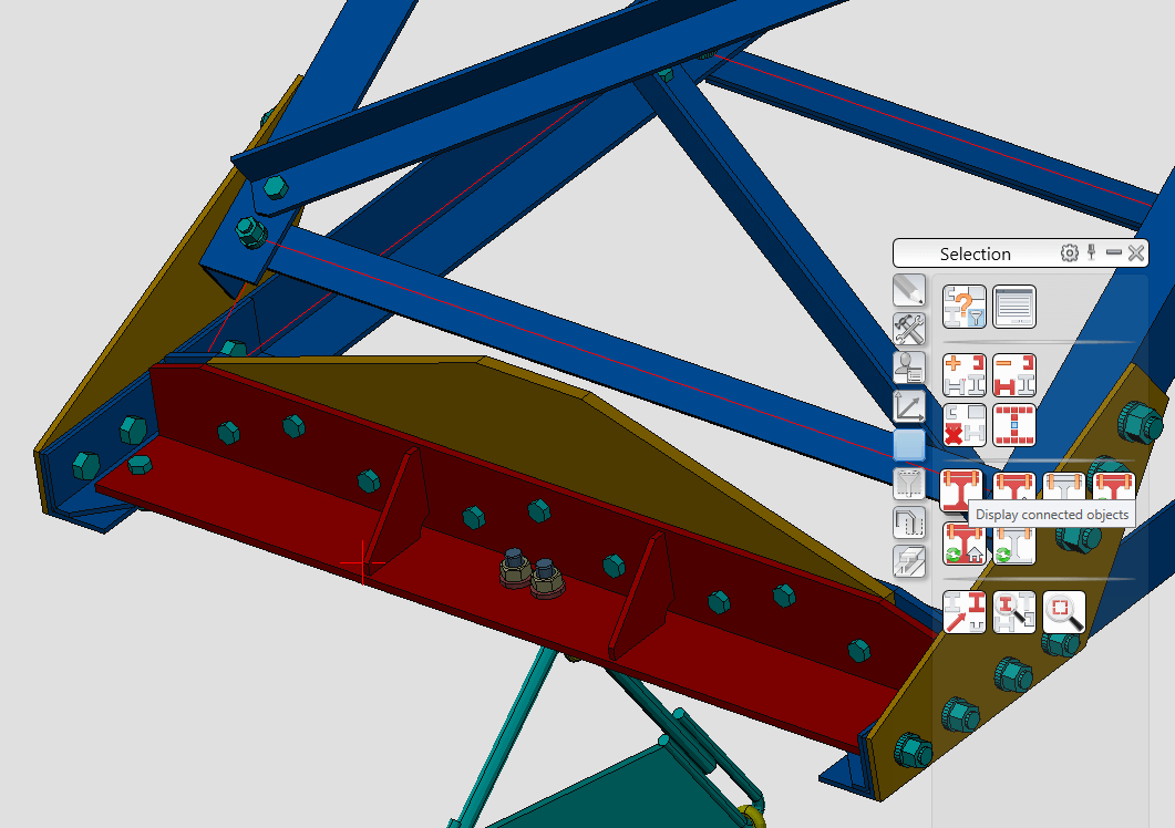
AS selection tools are quite handy. Selected objects can be easily color-coded for further manipulation. For example to copy or define all elements of the assembly, elements connected by a specific bolt, etc.
This is especially convenient at the model validation stage. Such a selection is not discarded when the mouse is clicked in an empty area of the screen, which is useful when selecting a large number of objects. However, if the selection is not dismissed after performing manipulations, this can often cause accidental changes in the model, such as unintentional copying, deletion, etc.
Tekla:
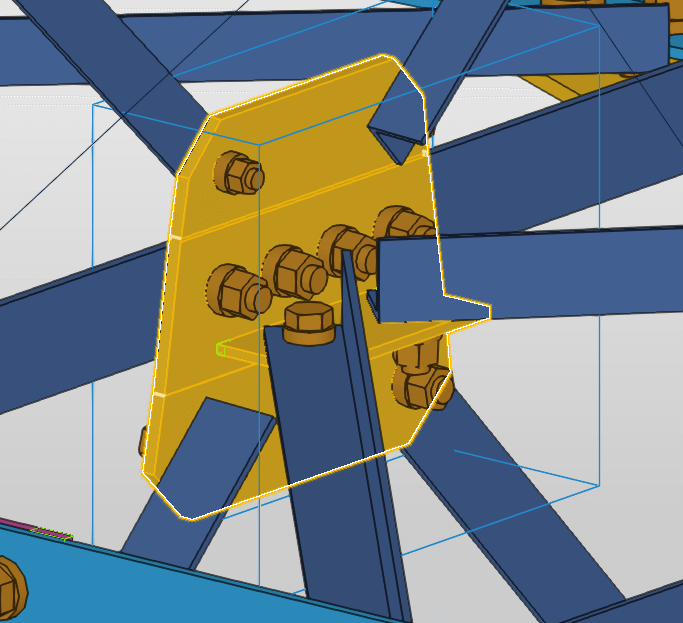
Tekla’s selection function is implemented through buttons on the selection toolbar and through selection filters. These tools are designed a little differently and are more elaborate, therefore safe to work with. For example, there is simply no risk of accidentally selecting a different type of object when working in bolt selection mode. While using AS selection filters allow adding objects of different types to the selection.
Object types
AS:
Profiles and plates are different types of objects. Therefore the user can filter them and make changes to their general properties in one click, without creating a specific filter request. This is very convenient when you need to quickly select a large number of objects of the same type regardless of their specific attributes. It works the same way with bolts, anchors, etc.
Tekla:
In Tekla, such objects as plates, bent plates, and profiles are the one object type, called “Part”. Bolts, openings, anchors, and others are defined by the “bolt group” type. This significantly complicates filter adjustments. Thus, filtering only openings or only bent plates, for instance, becomes more difficult, due to the necessity to set a specific multi-line query. Luckily, such a query can be saved once and used in the future.
Grouping objects
AS:
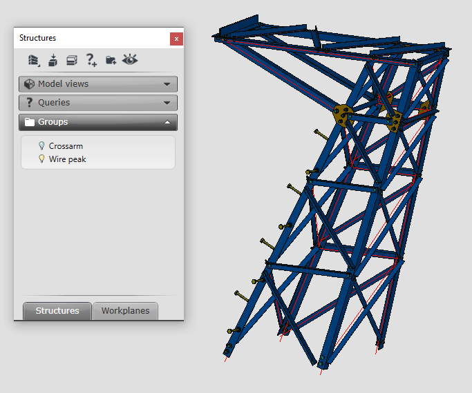
Since the program interface is based on AutoCAD, Advance Steel has adopted many of its features and tools, including layers. Different types of model objects are automatically detected and grouped on their layer. If the need for grouping different types of objects with each other occurs, It is also possible to group such objects manually. Groups of objects can be adjusted, but newly created elements do not automatically fall into the correct group.
Tekla:
In its turn, Tekla operates with so-called phases. Roughly speaking, phase is a kind of analog to layer. Phase or stage breaks down a model into blocks, most commonly to indicate the assembly sequence. You can create reports and views, hide objects, and copy objects from other models according to the phase number. When working in the mode of a certain phase, all objects automatically fall into this phase. This function is implemented in a very simple but effective and convenient way.

Bent plates
AS:
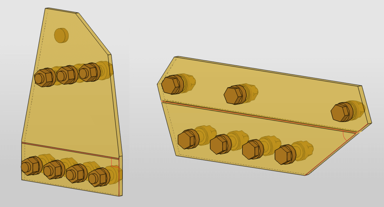
In some versions of the program, there are problems with bent plate drawings, if the plate vertex coincides with the bending line. The plate contour disappears, and only the bending line itself is displayed on the drawing.
Changing bent plate thickness also often leads to errors in NC files and incorrect display. This happens due to the direction of the z-axis during the creation of each of the parts of the bent plate. To change such plate thickness, It is better to separate its parts, and after changing their thicknesses, merge them again. In this case, the numbering of the part disappears. It is also impossible to change the geometry of the bent plate completely without separating its parts. Aside from these, the creation of bent plates with a correctly selected UCS does not cause problems.
Tekla:
Creating bent plates in Tekla is not very convenient because of the need to maintain a gap between the parts of the plate. At the same time, it is not clear how to determine the size of this gap. In later versions of the program, this issue was partially solved, but only for plates with the bending line perpendicular to the plate edge. For the rest of the plates, the challenge remains. We also faced the problem when a bent plate turned into a zero mass element during the merging of plate parts. A similar problem emerged with correctly created plates after they were copied or mirrored. The possible solution is to separate the parts of the plate, remove all bolts and then merge them again. It is also not possible to change the geometry of a bent plate completely without separating it.
Bolts
AS:
For the correct bolts orientation, they must be created on the desired plane initially, since it is impossible to change the orientation of the bolt after its creation, except to invert it. In AS bolts can exist in the model separately from profiles. Therefore can’t be deleted/copied by the delete/copy part command. Thus, such bolts fall into all lists at the same time since they do not belong to any of the elements of the model.
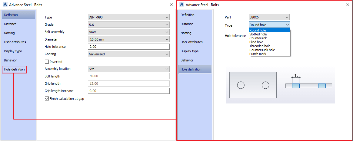
Bolt affiliation is determined by the position of its head. To add or exclude a new element to the connection, you must use the tool “Add / Delete objects to connection”. Also in AS it is possible to adjust the parameters of the openings for any occasion.
Tekla:
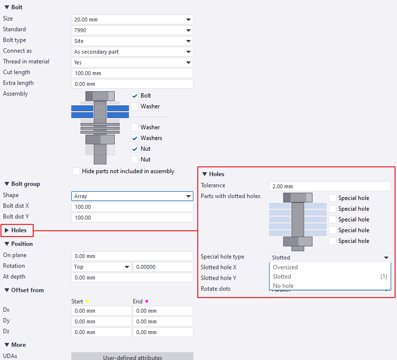
Unlike AS, Tekla allows changing existing bolt orientation whenever. Also, bolts do not exist separately from profiles or plates and are deleted/copied together with their elements.
Bolt affiliation to an element is determined by the order in which elements are selected when it is set. To add or exclude a new element to the connection you need to re-select all its elements in the correct order.
Bolt length
The length of the bolt depends on the overall thickness of the elements included in the bolt kit (nuts, washers. etc.) and on the thickness of the connected elements pack. The size of the gap between the connected elements also affects the length of the bolt. When modeling structures such as power transmission towers, it is impossible to avoid gaps between some elements in the model. But since these gaps will not exist in reality (the parts are tightened with bolts during installation), it becomes necessary to forcefully adjust the length of the bolt in the model. When connecting a large number of elements, the thickness of the zinc coating/paint must also be taken into account.
AS:
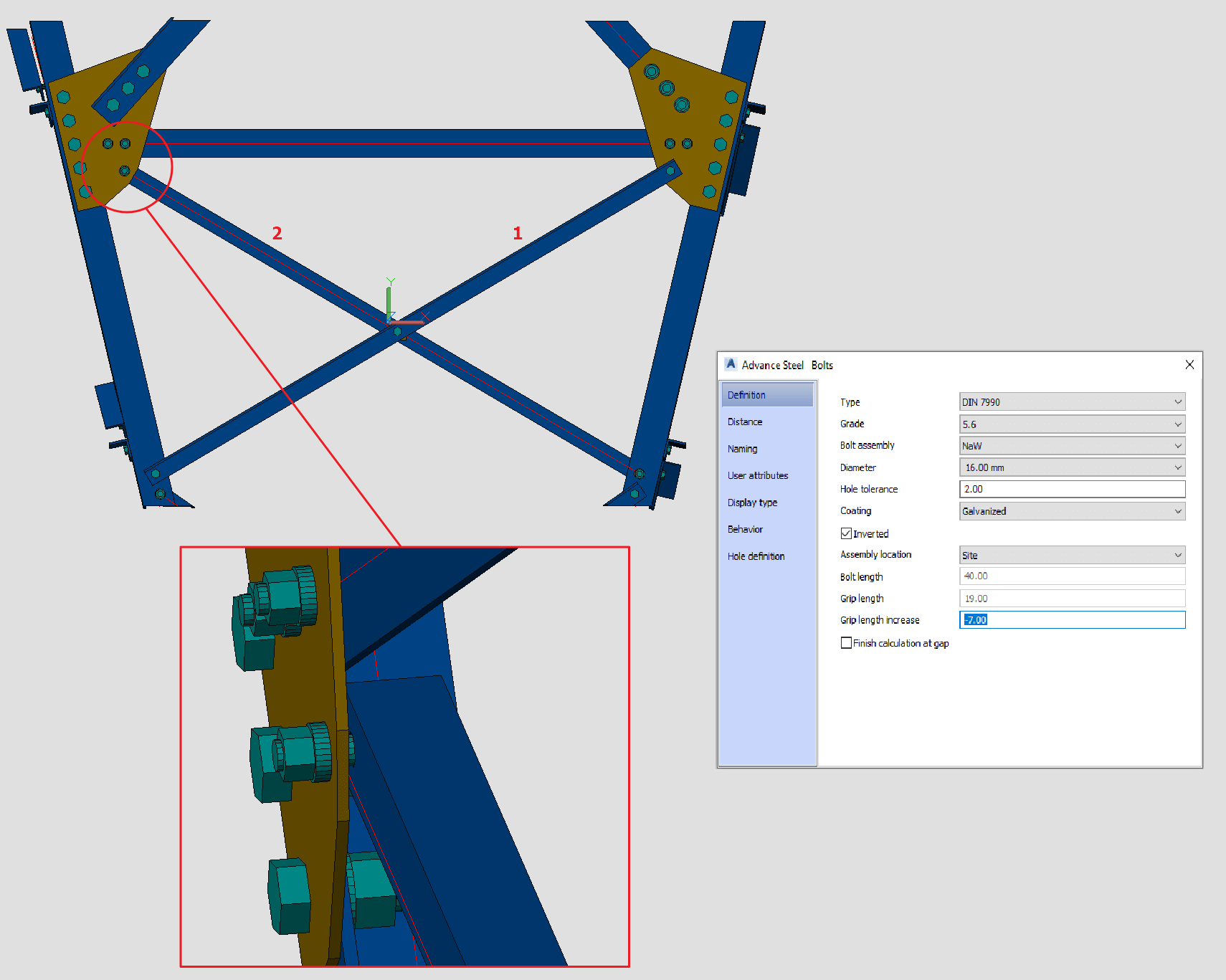
Diagonal 1 on the image is attached to the outer face of the column. Diagonal 2 is attached to the inner face of one. In its turn, connecting gusset plate is attached to the outer face of the column. Respectively, diagonal 2 in the model is separated from the gusset plate by a gap equal to the thickness of the column. Accordingly, the bolt that joins diagonal 2 with the gusset plate is longer than necessary, since the gap is included in the calculation of its length. This can be fixed by entering the required value in the “grip length increase” field (in our case, this value is the thickness of the column). In the future, when changing the thickness of the connected elements, the length of the bolt will change automatically, thanks to this adjustment.
Tekla:
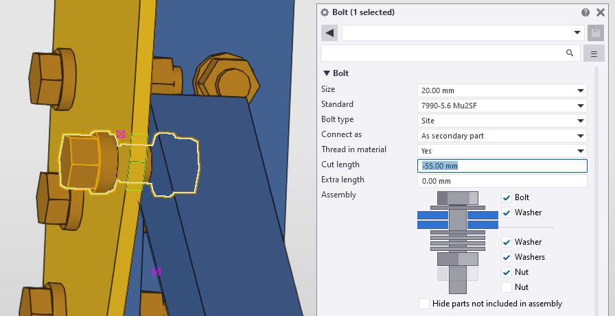
In a similar situation, you can fix the bolt length by entering data in the “cut length” field. However, to do so you need to calculate the bolt length for a specific situation and enter this value with a negative sign. Thus, in the future, when changing the thickness of the connected elements, the length of the bolts will remain the same as specified in the “cut length” field and will not adjust automatically.
Bolt groups
AS:
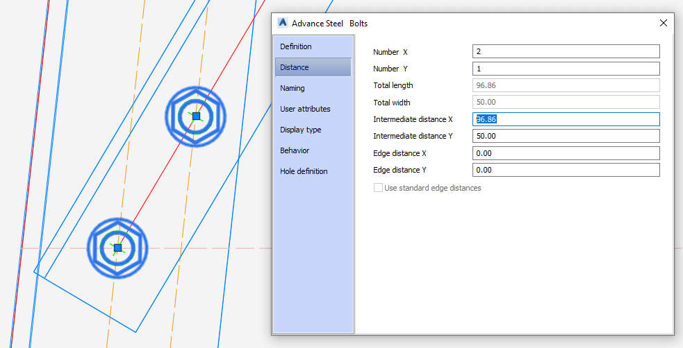
“Handles” not only determine the direction of setting a group of bolts but also define the position of the first and last bolt in the group without entering any values from the keyboard. “Intermediate distance X” on the image was determined automatically.
Tekla:
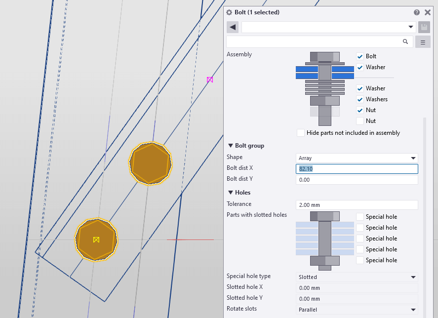
The position of the “handles” also determines the direction in which the bolt group is set. But the distance between the bolts in the group needs to be entered manually from the keyboard. This leads to the need for additional measurements.
Welding
AS:
Allows creating an assembly in one click using the “weld point” tool by selecting a large number of elements. This is a fast and convenient way since it makes no sense to set up each specific weld bead (joint). Most likely the automatic welding symbol will not look correct on the drawing anyway, and in case of an error or changes, the entire drawing needs to be updated. Therefore, it is better to mark welding on the sheet manually. With a well-tuned weld symbol block, this won’t be a problem. When copying an element, you must first select all the parts attached to it, as well as bolts and welds.

Tekla:
Just like in AS, customizing each weld through the model is not a solution that will make life easier. Even though it works well sometimes, you will probably still need to adjust the automatic weld symbol in the drawing. Tekla allows assigning welding only to each element of the assembly individually. Although it is time-consuming, especially on large structures such as welded railings or handrails, this approach is much more similar to the real structure assembling process.
Features
AS:
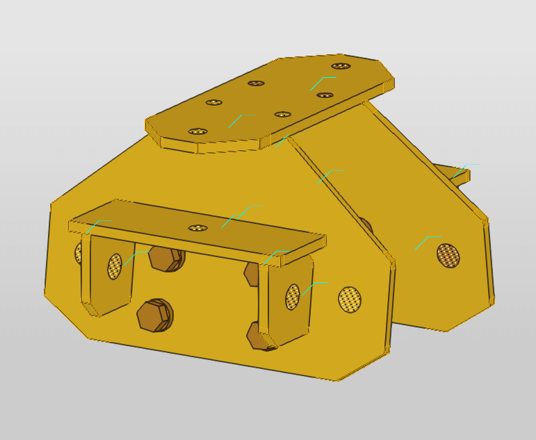
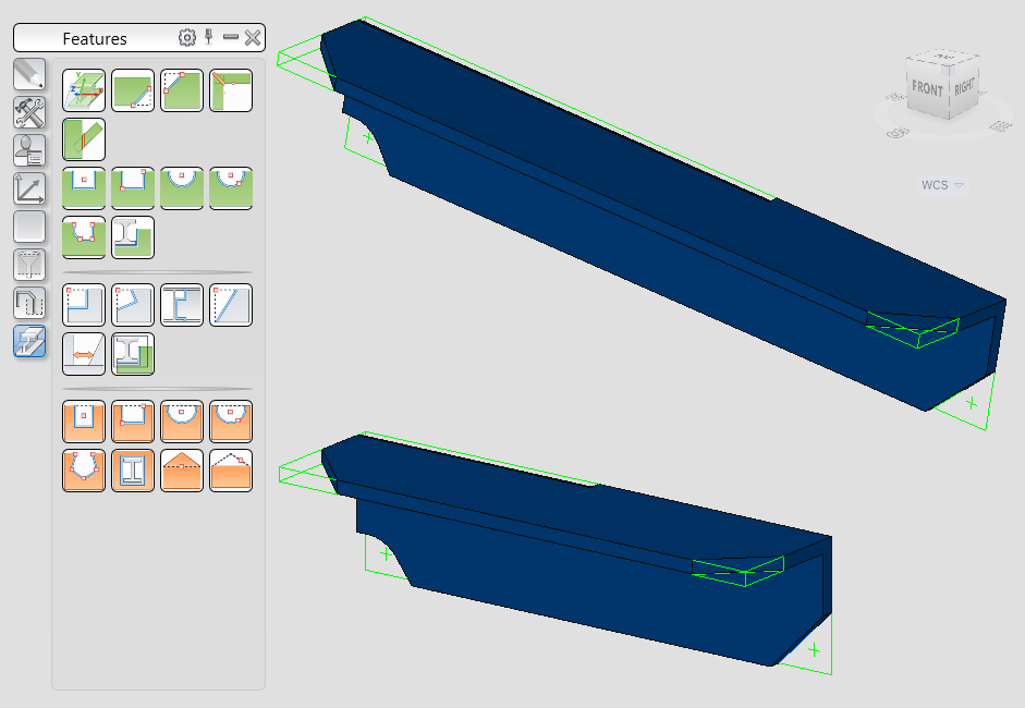
Advance Steel provides a variety of tools for machining. Treatments or machining’s of existing basic objects (eg profile cut or corner cut) are displayed as green frames. A machining object is a part of the base profile or plate. Being attached to its object, it can not exist separately. When the base object is deleted, all of its machining objects will also disappear
Image from bottom to top:
A corner with machining’s before manipulations;
A corner with machining’s after manipulations (lengthening, moving).
Tekla:
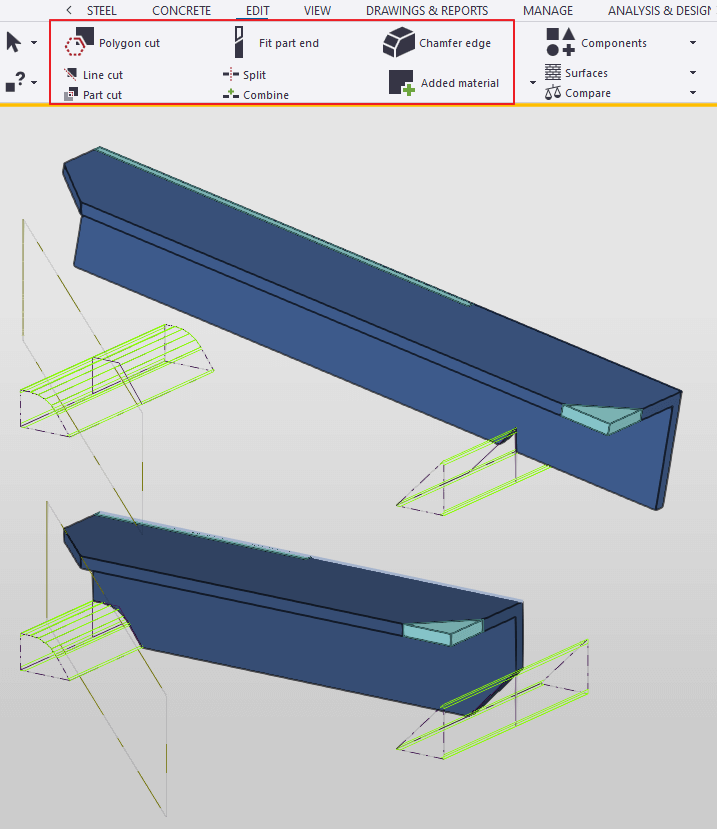
The display of some machining’s looks a little bulky, so with a large number of machining’s, it can be difficult to understand which element each machining belongs to. Some machining’s are displayed as objects with a solid fill, which can obstruct visual perception. Also when copying, mirroring or changing the position of an element, its machining’s may not be copied along with it. This entails additional adjustments and maybe even errors.
Image from bottom to top:
A corner with machining’s before machining;
A corner with machining’s after manipulations (lengthening, moving).
Collision check
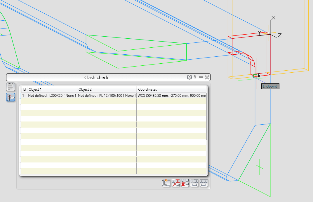
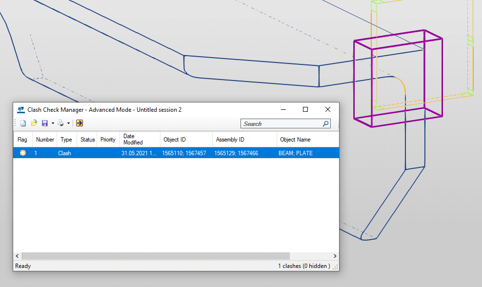
In general, both products cope equally well with collision detection in the model. Worth mentioning that AS allows users to snap to the boundaries of the collision. It makes it possible to measure the size of the collision in a particular place and more accurately adjust the positions of elements. Meanwhile, Tekla does not provide such an option, the program simply highlights collision place.
Sometimes several elements may have an infinitesimal overlap, imperceptible to the eye. “Clash check” will certainly point you to this issue, but there is still the risk of missing it. When modeling complex structures, there is a huge number of such acceptable and unavoidable collisions. From a construction point of view, they are harmless and won’t affect anything. But reports may include hundreds of these, making it easy to miss one, which will cause numeration and documentation problems. This is a common problem for AS beginners, while Tekla does not allow accidental copying of an overlaying element.
AS:
Tekla:
Components and parametric connections
Both programs operate with so-called components or parametric connections (joints). These are composite objects that include base elements and dependent elements. Such composite object obeys the joint rule and adapts to model changes.
AS:
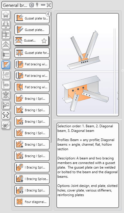
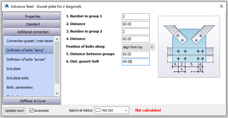
Offers a wide range of the most common connections with a pretty nice menu interface and clear instructions on using the component. Allows users to create copies of connections in a group (master-slave joints), so the copies depend on the master joint. When changes are made to the master joint, changes are made to the dependent joints as well. This feature especially comes in handy when working on multi-span structures with many repeatable joints.
Tekla:
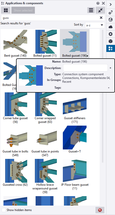
Represents a wide range of components, but it is often difficult to understand how to use a component without special guidance. Unlike AS, there are no comments and visual cues in Tekla’s component editing window.
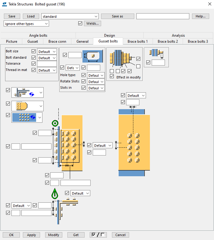
Unfortunately, for elements located in different planes, both AS joints and Tekla components perform equally poorly. Both programs allow the creation of custom connections, but this is not an easy task for a new user.
User profiles
AS:
Creating a bent section from a simple polyline takes almost no time. A bent object can be easily created right in a model space using polyline and the “Folded Beam” command.
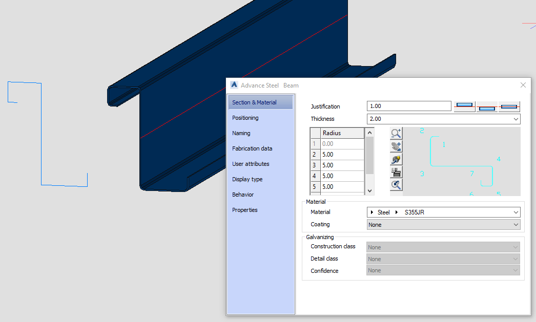
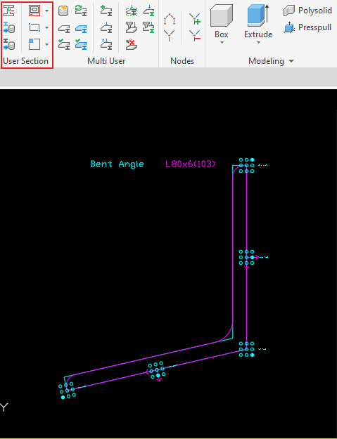
The second way to create a non-standard profile is to create a contour of its cross section in a separate file and then load it into the project. Such a profile behaves the same way as any standard AS profile, has the same machining tools, can perform as an element of a joint, and so on. However, this way requires special attention and knowledge.
Tekla:
Provides many ways to create a custom profile: contouring with a polygon, with a plate, or with a downloadable dwg file. The profile creation process is very simple and requires a minimum of actions.
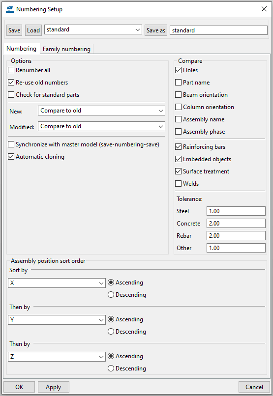
Numbering
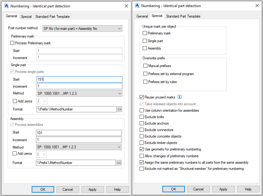
The process of numbering model elements is almost the same. The basic numbering principle is to find identical elements and assign the same numbers to them.
AS:
The most massive part of the assembly becomes the main (unless another main part is specified by the user manually). AS performs a comparison of elements to determine the number of identical ones and then merges them into groups. Groups with more elements get the lowest numbers.
Sorting can be done by user-defined attributes. If no individual elements are selected during the process, all elements of the model will be numbered. First numbers are assigned to the profiles, then to the plates.
The AS functionality is able to identify objects with duplicate part numbers, identify differences between two objects, display objects with the same part number, and objects with different part numbers, and mark unattached parts or parts without a number.
Tekla:
The main part is determined by the selection order when the assembly is created. The default sort order is XYZ where X, Y, and Z are the coordinates of the main part in the assembly.
Sorting is based on the location of the assembly’s centroid. Tekla finds the centroid for each assembly and compares it in the given order. Sorting can also be done by user-defined attributes. When starting the numbering process, the entire model is always checked. Same as AS, Tekla provides the function of determining differences between objects. There is also a convenient setting for displaying parts and mark numbers in model views.
Specifications and Drawings
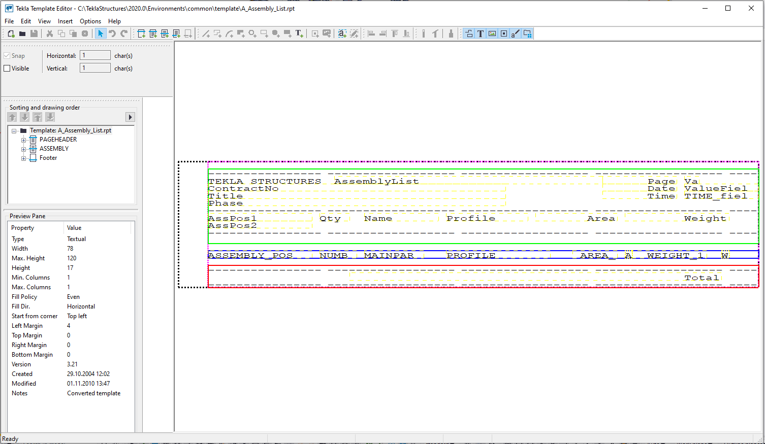
Specifications
Both programs have standard editable specification templates and allow users to create custom templates. In general, the differences are minimal, unless AS has a more familiar interface for the average user.
AS:

Tekla:
Drawings
AS:
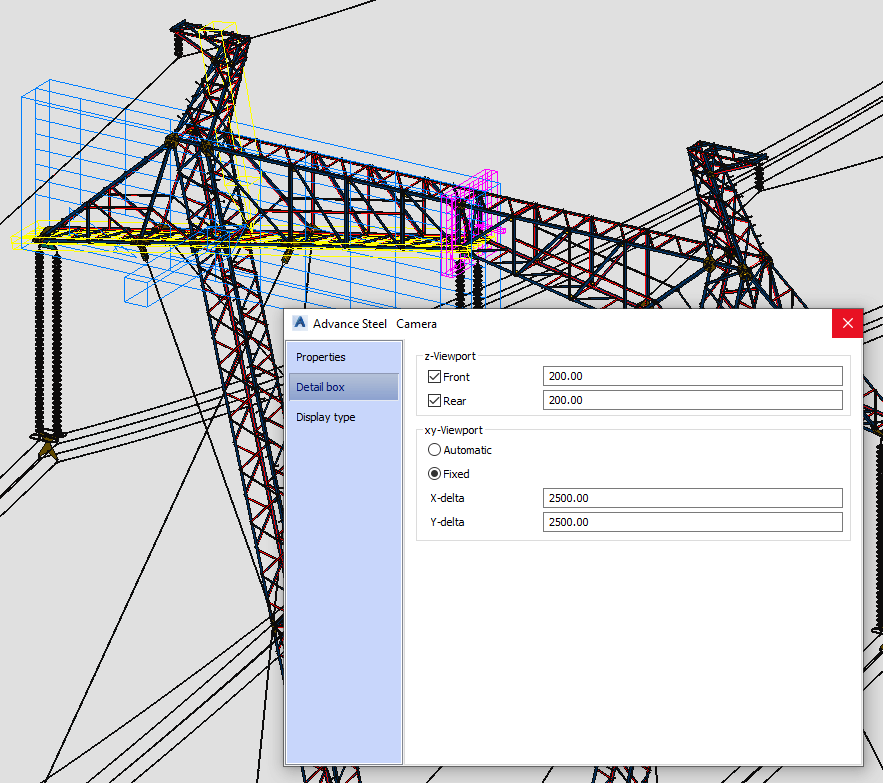
GA drawings are created from cameras. The camera is a separate visible object of the model, which makes it possible to visually determine the location of the view in the model, the boundaries of the view, and its depth.
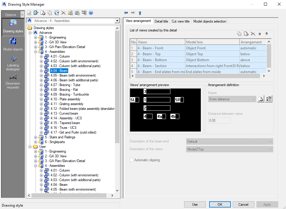
A drawing style is a set of settings that includes the direction of view, its visible area, criteria for model elements selection, and the way they are presented in the drawing. As well as the rules for marking and dimensioning.
In AS, a separate style must be set up and saved for each type of drawing. If the need to change the style for a particular view occurs, that view needs to be updated.
Correctly preset style minimizes manual drawing adjustments in the future. That speeds up work, especially when drawing a large number of standard parts. However, setting up a drawing style in AS is not an easy task. Successful customization requires a profound understanding of the program algorithms.
In AS, it is possible to open several drawings simultaneously. This allows parallel work with the model and drawings since the drawings are extracted to separate associated with the model dwg files. Unfortunately, drawings are not updated automatically. As soon as changes are made to the model, a notification to update the views in the drawings manually emerges. Sometimes this leads to the accidental release of irrelevant documentation.
Tekla:
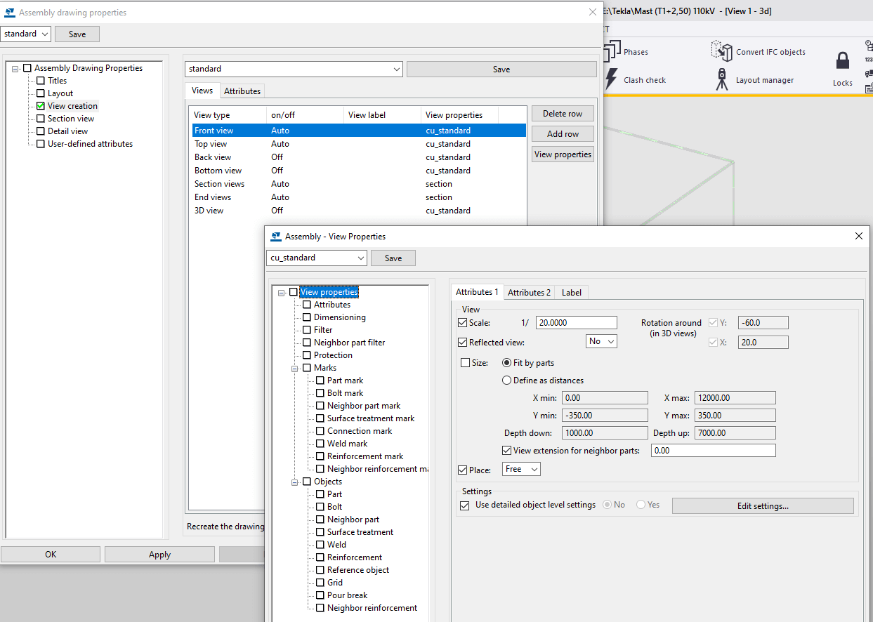
GA drawings are created based on a list of preset views. Their depth and visibility limits can later be adjusted directly on the drawing.
In Tekla, the drawing style can be read directly from the view and customized for each individual view if necessary. Therefore, there is no need to create a new drawing style each time. A three-level system of settings (sheet, view and single part) allows for getting the needed result quickly and efficiently.
Tekla does not allow opening multiple drawings at the same time, nor does it allow working simultaneously in the model and in the drawing. The drawings themselves are located directly in the project file and are updated automatically when changes are made to the model.
UCS (User Coordinate System)
In order for the assembly drawing or the detail drawing to be in order, the main view of each part in the drawing needs to be determined according to the unified principles.
In both programs, all elements in the model are automatically assigned their own local UCS.
AS:
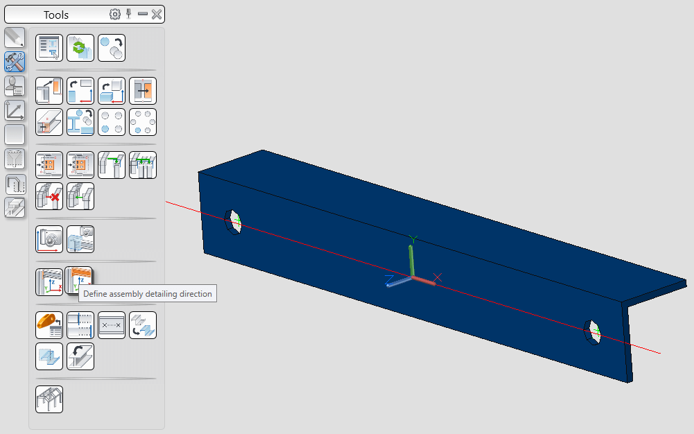
An element’s internal UCS can be easily reassigned. Usually, before the details are placed on the drawing, the specific main view for each is assigned
Tekla:
The local coordinate system directly affects the values of the position fields in the properties dialog boxes for beams and columns. If the direction of the UCS (work plane) is changed, the values of the position fields change also.
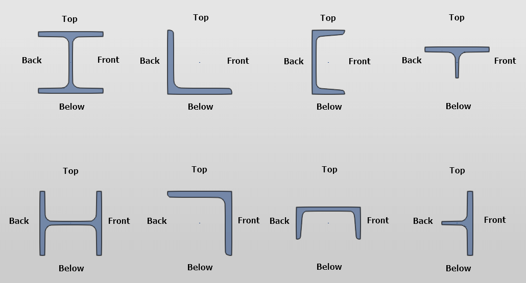
Each detail has 4 sides – top, front, backside, and bottom. The names of the sides remain the same when the details are rotated relative to the reference line. So, when rotated, the “Top” side will still be called “Top” even though it’s no longer facing up. This leads to difficulties in determining and assigning the orientation of the main view of the part in the drawing. Each part needs to be rotated around its axis manually on the drawing, which reduces the speed of work.
The function of cloning drawings is definitely a huge advantage of the program. It comes in handy when there are several similar parts or assemblies in the model; when you want to simplify editing; when several similar parts have different position numbers, or when a lot of manual changes need to be made to the drawing.

Conclusion
Both programs cover most of the needs for steel structure design and detailing. Due to its long history in the steel structures industry, Tekla has a larger user base and more market recognition compared to Advance Steel.
Also, Tekla has many advantages due to the ease of working with drawing views, working with sections, and callouts, not to mention an excellent document management system, and the ability to handle large models.
Advance Steel is a younger program with less market share and recognition. But the fact of AS acquisition by such a serious market player as Autodesk can’t be ignored. This gives reason for confidence that the AS market share will grow significantly, as well as the program’s recognition.
The interface of this product is built on the basis of AutoCAD, which makes it much easier for new users to work with than Tekla. A familiar set of tools and high compatibility with Revit also give a substantial advantage to AS. Furthermore, AS is way more configurable for non-programmers compared to Tekla.
There is nothing perfect in this world, and there is no software to be unanimously declared the best one for steel detailing. But since you have got a choice, try different options to make a deliberate decision.
Getting software training is always a good idea to get to know the product better. Check out AEC soft articles and forums, including official Autodesk and Tekla websites. There are many useful tips and instructions over there that will definitely help you to make the right choice.
After all, most of the software on the market offers quite similar functionality with slight differences in implementation. What makes the real difference is your skills and your knowledge.

